Hydraulic damper for elevator

A technology of hydraulic shock absorber and hydraulic shock absorber, which is applied to liquid shock absorbers, elevators in buildings, shock absorbers, etc. Small depth dimension, the effect of reducing construction cost

Inactive Publication Date: 2009-12-09
HITACHI LTD +1
View PDF1 Cites 32 Cited by
  • Summary
  • Abstract
  • Description
  • Claims
  • Application Information

AI Technical Summary

Problems solved by technology

[0006] However, in the prior art described above, the operating stroke of the conical (conical) control rod has the same value as the stroke of the lowermost plunger, so the value equivalent to twice the stroke is greater than the overall height of the h

Method used


Image

  • Hydraulic damper for elevator
  • Hydraulic damper for elevator

Examples


Embodiment Construction

[0041] Embodiments of the hydraulic shock absorber for an elevator according to the present invention will be described below with reference to the drawings.

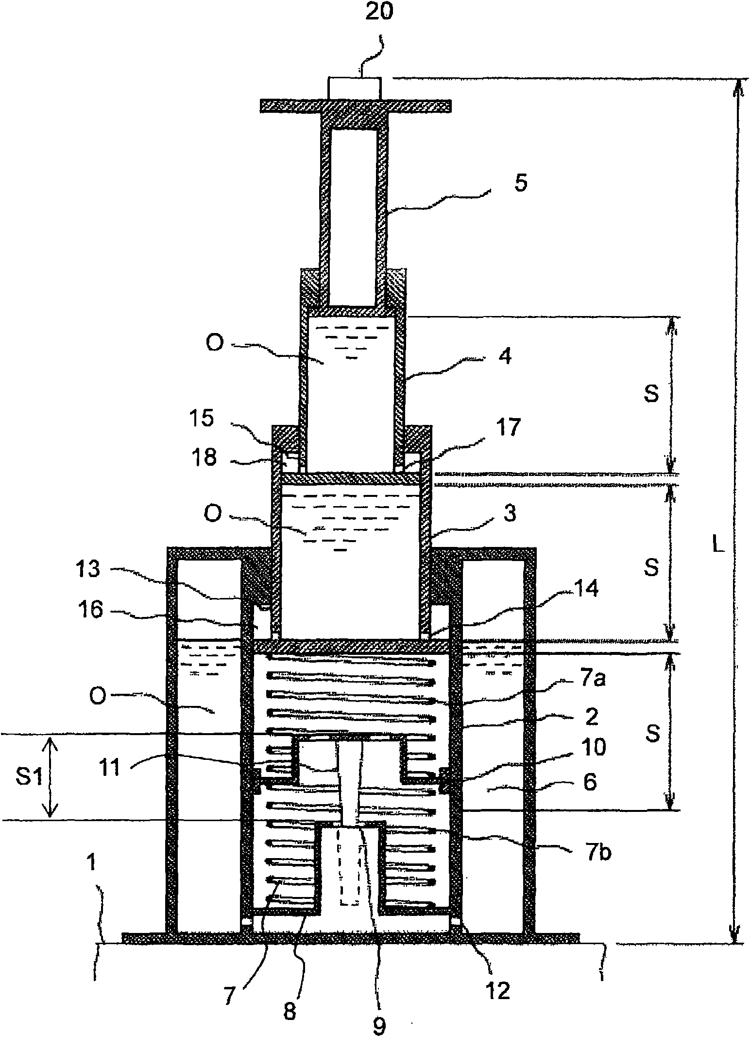
[0042] figure 1 It is a longitudinal sectional view showing one embodiment of the elevator hydraulic shock absorber according to the present invention, figure 2 is a schematic diagram showing the compression state of the hydraulic shock absorber.

[0043] Such as figure 1 As shown, the hydraulic shock absorber for an elevator in this embodiment is composed of a hydraulic cylinder 2 and a plurality of plungers. The plug 3, the second plunger 4 and the third plunger 5 are fitted in the hydraulic cylinder 2 in a manner that can expand and contract in the up and down direction, and the diameters of the plurality of plungers decrease sequentially from the outside to the inside, and they are stacked in a concentric manner.

[0044] The hydraulic cylinder 2 has: an oil tank 6, which is arranged on the outside of the hydra...


PUM


Abstract

The invention provides a hydraulic damper for an elevator capable of reducing whole height. The hydraulic damper for the elevator provided by the invention comprises a hydraulic cylinder and a plurality of plungers. The hydraulic cylinder is vertically arranged in an elevator pit of a lift passage and filled with hydraulic oil. A plurality of plungers are jogged into the hydraulic cylinder in a way of stretching up and down, diameter is gradually reduced from outside to inside, and the plungers are concentrically overlapped with each other. In addition, an orifice for the hydraulic oil to pass through when the plungers drop, a slender conical member, a front end of which is loosely inserted into the orifice, and a returning spring that enables the dropped plungers to return a primary position are arranged in the hydraulic cylinder. In the hydraulic damper for the elevator, the returning spring is composed of a first spring and a second spring in a way of dividing one into two up and down, at the same time, a circular disc with the slender conical member can be arranged between the first spring and the second spring in a way of moving up and down.

Description

technical field [0001] The invention relates to a hydraulic buffer for an elevator. The hydraulic buffer for an elevator is arranged at the bottom of an elevator hoistway. The impact force is moderated with the appropriate deceleration by the hydraulic buffer, so that the elevator stops safely. Background technique [0002] Under normal circumstances, the descending position of the lifting body of the elevator will not exceed the normal stop position of the lowermost floor, but when some abnormality occurs in the elevator, the descending position of the lifting body may exceed the normal stopping position of the lowermost floor. Therefore, in order to alleviate the impact force of the lifting body so that the lifting body can be safely stopped when the above-mentioned abnormality occurs, according to regulations, it is obligatory to install a buffer at the bottom of the hoistway of the elevator. As this kind of shock absorber, there is known a hydraulic shock absorber, whic...

Claims


Application Information

Patent Timeline
IPC IPC(8): B66B5/28B66B11/00F16F9/22F16F9/34
Inventor 渡边春夫座间秀隆宫田弘市平野薰蔀贤二增田胜太郎
Owner HITACHI LTD
Why Eureka
Try Eureka