Difunctional vane type hydraulic transformer controlled by motor

A hydraulic transformer and motor control technology, which is applied in the direction of fluid pressure converters, mechanical equipment, etc., can solve the problems of complex structure of plunger-type hydraulic transformers, limited application range of hydraulic transformers, and high oil filtering precision requirements, and achieves rich varieties and easy operation. The effect of precise control and small moment of inertia

Inactive Publication Date: 2010-12-29
SHANDONG JIAOTONG UNIV
View PDF4 Cites 0 Cited by
  • Summary
  • Abstract
  • Description
  • Claims
  • Application Information

AI Technical Summary

Problems solved by technology

[0003] Existing hydraulic transformers are basically plunger-type structures, with high working pressure above 20MPa and large flow range. They are generally used in high-pressure and large-flow hydraulic systems. They are used in medium and low-pressure hydraulic systems, and the efficiency is very low. , and the plunger hydraulic transformer has a complex structure, high processing precision, is sensitive to oil pollution, requires high oil filtration precision, and is expensive, so the application range of hydraulic transformers is greatly limited.

Method used


Image

  • Difunctional vane type hydraulic transformer controlled by motor
  • Difunctional vane type hydraulic transformer controlled by motor
  • Difunctional vane type hydraulic transformer controlled by motor

Examples


Embodiment Construction

[0020] The present invention will be described in detail below in conjunction with the accompanying drawings and embodiments.

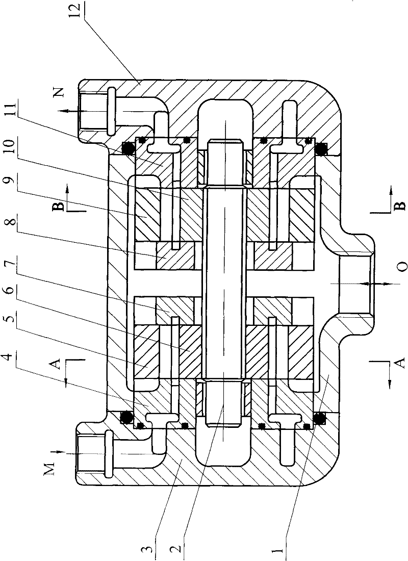
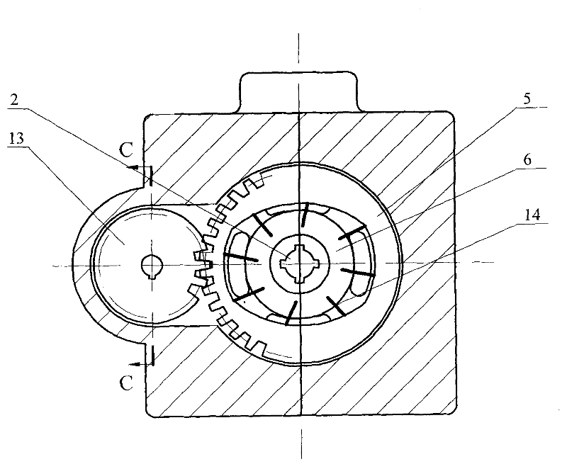
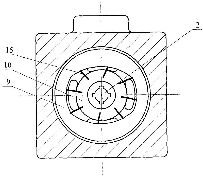
[0021] Such as figure 1 , 2 , 3, and 4, a motor-controlled double-acting vane hydraulic transformer of the present invention is mainly composed of a housing 1, a rotating shaft 2, a left end cover 3, a first group of flow plates 4, 7 and a first fixed 5, the first rotor 6, the second set of flow plates 8, 11, the second stator 9, the second rotor 10, the right end cover 12, the gear 13, the motor 16, the first set of blades 14, the second set of blades 15, etc. The centers of the first rotor 6 and the first stator 5 are fixed and coincident, the width of the first rotor 6 is slightly smaller than the width of the first stator 5, the first rotor 6 is installed in the first stator 5, and the first rotor 6 is installed in the first stator 5. One end of a group of blades 14 is placed in the blade groove of the first rotor 6, and the other end is in cont...


PUM


Abstract

The invention discloses a difunctional vane type hydraulic transformer controlled by a motor, comprising a housing, a rotation axis, a left end cap, a port plate, stators, rotors, a right end cap, a gear, a vane, a motor, etc. The invention is characterized in that the centers of the rotor and the center of the stator are fixed and coincident, and the vane is arranged along the radial direction of the rotor; one rotor is connected with the left half axis of the rotation axis in a matching mode by a spline, and the other rotor is connected with the right half axis of the rotation axis in a matching mode by a spline; the outer ring of one stator is made into a gear form by taking the major radius arc center as the center and ranging within 150 degrees, and one stator and the gear form a gear transmission pair; the gear is installed on the output axis of the motor, the motor is arranged on the housing, and the port plate is arranged on the rotation axis and is tightly pressed on the leftside surface and the right side surface of the rotor; and the left end cap and the right end cap are fixed on the housing via bolts. The invention has the beneficial effect that the invention can adjust the voltage of a constant-voltage network system to any value within induced pressure variation range in the way of no throttle loss, and can be used in medium-voltage hydraulic systems and high-voltage hydraulic systems.

Description

(1) Technical field [0001] The invention relates to a hydraulic transformer, in particular to a motor-controlled double-action vane hydraulic transformer, which belongs to the mechanical field. (2) Background technology [0002] A hydraulic transformer is a hydraulic component that realizes pressure conversion in hydraulic transmission. The hydraulic transformer can efficiently convert the input hydraulic energy under a given pressure into the output hydraulic energy under another pressure. Using it can realize the independent control of multiple loads in the constant pressure network, and also make the energy reverse flow , not only can drive linear loads without throttling loss, but also can drive rotary loads. [0003] Existing hydraulic transformers are basically plunger-type structures, with high working pressure above 20MPa and large flow range. They are generally used in high-pressure and large-flow hydraulic systems. They are used in medium and low-pressure hydrauli...

Claims


Application Information

Patent Timeline
Patent Type & Authority Patents(China)
IPC IPC(8): F15B3/00
Inventor 臧发业张玉波孔祥臻郑澈戴汝泉
Owner SHANDONG JIAOTONG UNIV
Why Eureka
Try Eureka