Screw applied to composite material

A composite material and screw technology, applied in the direction of screws, threaded fasteners, connecting components, etc., can solve problems such as low locking force, toppled partition walls, unsatisfactory combination of self-tapping screws and metal plates, etc., to achieve locking The effect of fast speed and improved safety of use

Inactive Publication Date: 2011-07-06
陈河田
View PDF0 Cites 0 Cited by
  • Summary
  • Abstract
  • Description
  • Claims
  • Application Information

AI Technical Summary

Problems solved by technology

[0007] But its biggest disadvantage is that when the self-tapping screw 2 locks into the metal plate, because there is a drilling portion for drilling, the same will drill the metal plate, and at the same time, the aforementioned cutting wing 211 also cuts the metal plate A groove B0 is formed on the B surface until the cutting wing 211 breaks
[0008] Finally, when the screw teeth 210 of the rod portion 21 are screwed with the metal plate, the screw teeth 210 of the rod portion 21 are not screwed with the calcium silicate plate A, but as the metal plate of the composite material of the partition wall base material, its The average is about 0.6mm. When the drilling part and the cutting wing part pass through the metal plate, the combination between the self-tapping screw and the metal plate is not ideal. Moreover, the hole B0 caused by the cutting part 212 on the iron plate B will If it is larger than the bottom diameter of the screw teeth, the locking force will also be low, resulting in the poor locking effect of the calcium silicate board A
It is easy to cause the grouting to cause the partition wall to fall or leak due to poor locking

Method used


Image

  • Screw applied to composite material
  • Screw applied to composite material
  • Screw applied to composite material

Examples


Embodiment Construction

[0043] In the following, the structural composition and the effect that can be produced by the screw applied to the composite material of the present invention are described in detail as follows with preferred embodiments in conjunction with the accompanying drawings:

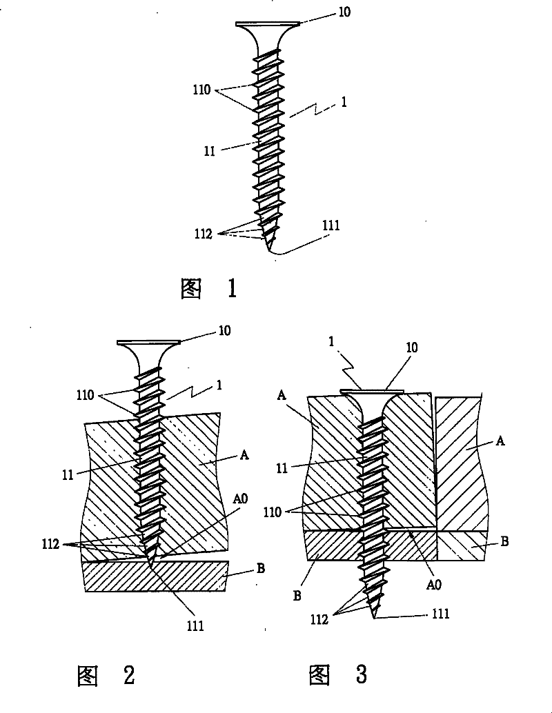
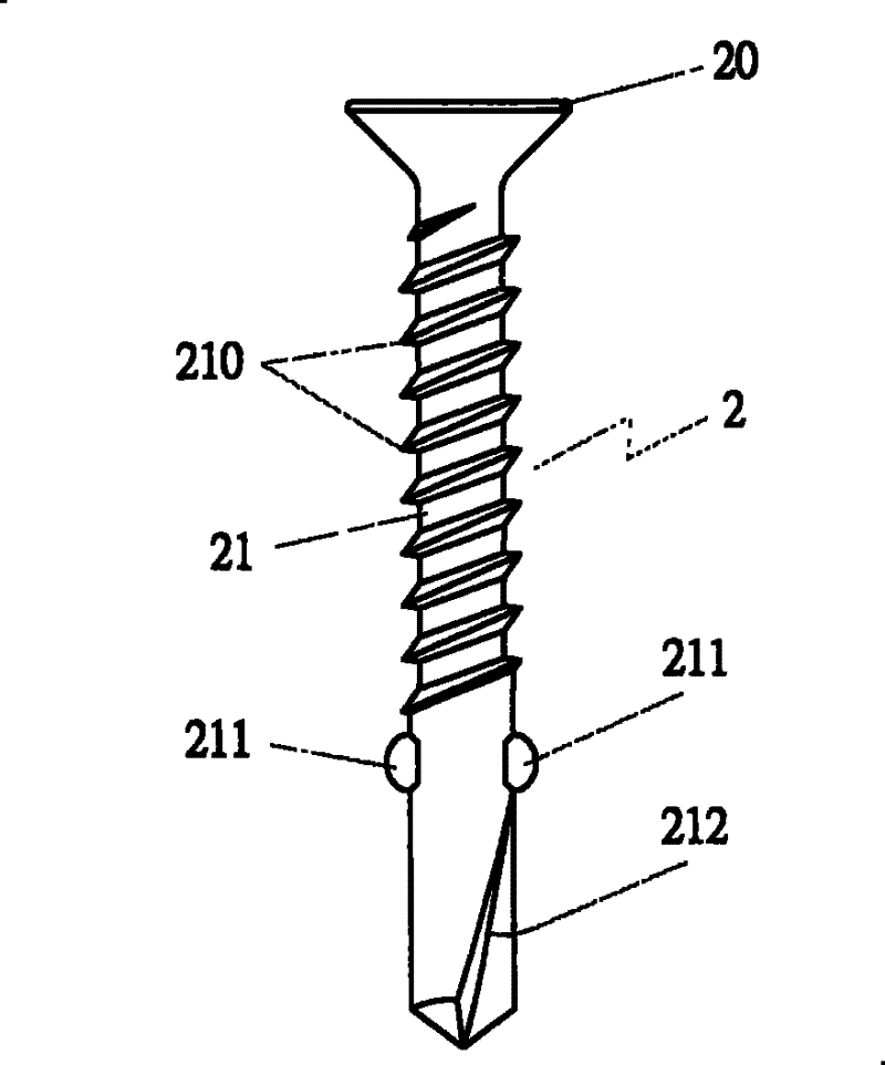
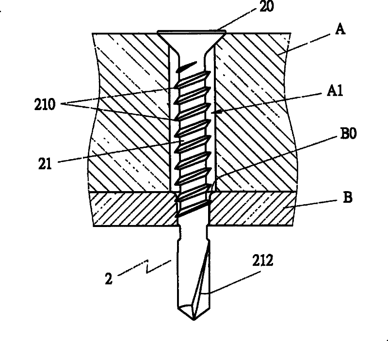
[0044] Such as Figure 6-10 Shown is a view and a cross-sectional view of Embodiment 1 of the present invention. Embodiment 1 of the present invention is applied to a screw 3 made of composite materials, including a cap 30 , a stem 31 and a cutting wing 34 .

[0045] The cap portion 30 is disposed on the top of the rod portion 31, and the cap portion 30 can be in any shape, and can cooperate with various locking tools. A plurality of cutting surfaces 301 are provided on one side 300 of the cap 30 , and the composite material can be cut by using the cutting surfaces 301 and the cap 30 can enter the composite material.

[0046] The rod portion 31 is provided with a thread section 310. The shape of the thread sec...


PUM


Abstract

The invention discloses a screw applied to composite material, comprising a cap part and a rod part. The cap part is arranged on the rod part and can be in any shape to be matched with various locking hand tools; the surface of the rod part is provided with a thread section, and the lower end is provided with a pointed end part; a cone-shaped part is upwardly formed on the pointed end part; sections of cut wing parts with same or different lengths are formed on the rod part or between the rod part and the cone-shaped part, wherein the cut wing parts of the lower end section or close to the cone-shaped part are thicker than the cut wing parts of the upper end section. The screw not only protects the structure of the composite material, but also solves the problem of the partition wall collapse or leakage which is resulted from grouting and poor composite material locking and improves the use safety of the composite material.

Description

technical field [0001] The invention relates to a screw used in composite materials, in particular to a screw capable of fully and rapidly locking composite materials and maintaining the structural integrity of the composite materials. Background technique [0002] At present, composite materials are generally used as the base material of the building partition wall, and the construction of the partition wall can be completed after pouring concrete into the base material, but generally the screws used for locking the composite material will be damaged by two The structure between composite materials composed of different materials causes gaps in the partition walls, and the screws that lock the composite materials make the problem of water vapor leakage from the partition walls unable to be solved. Generally, the existing screws 1, such as Figure 1~3 As shown, it is the most common pointed tail screw on the market, which includes: a cap 10, the cap 10 is arranged above the r...

Claims


Application Information

Patent Timeline
Patent Type & Authority Patents(China)
IPC IPC(8): F16B25/10
Inventor 陈河田
Owner 陈河田
Why Eureka
Try Eureka