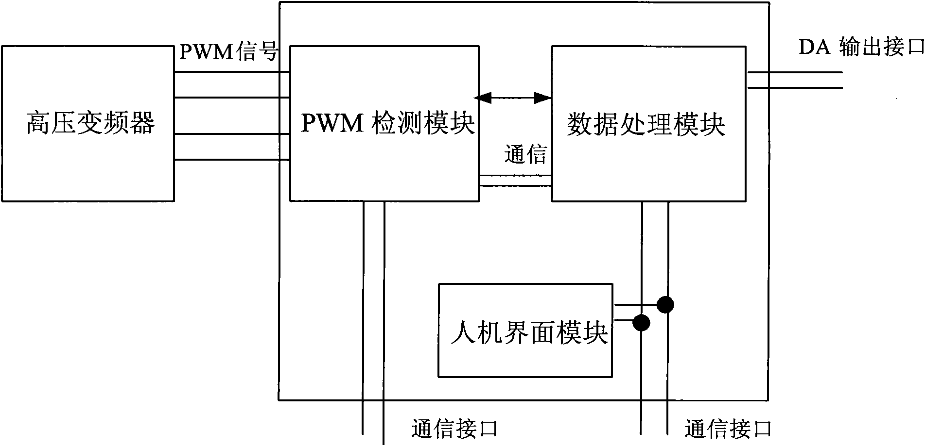
Test system of high voltage frequency converter
A high-voltage frequency converter and testing system technology, applied in the testing field, can solve the problems of insufficient power unit protection, increased safety detection, energy consumption, etc., to achieve the effects of improving testing efficiency, improving testing efficiency, and reducing energy consumption
- Summary
- Abstract
- Description
- Claims
- Application Information
AI Technical Summary
Problems solved by technology
Method used
Image
Examples
Embodiment 1
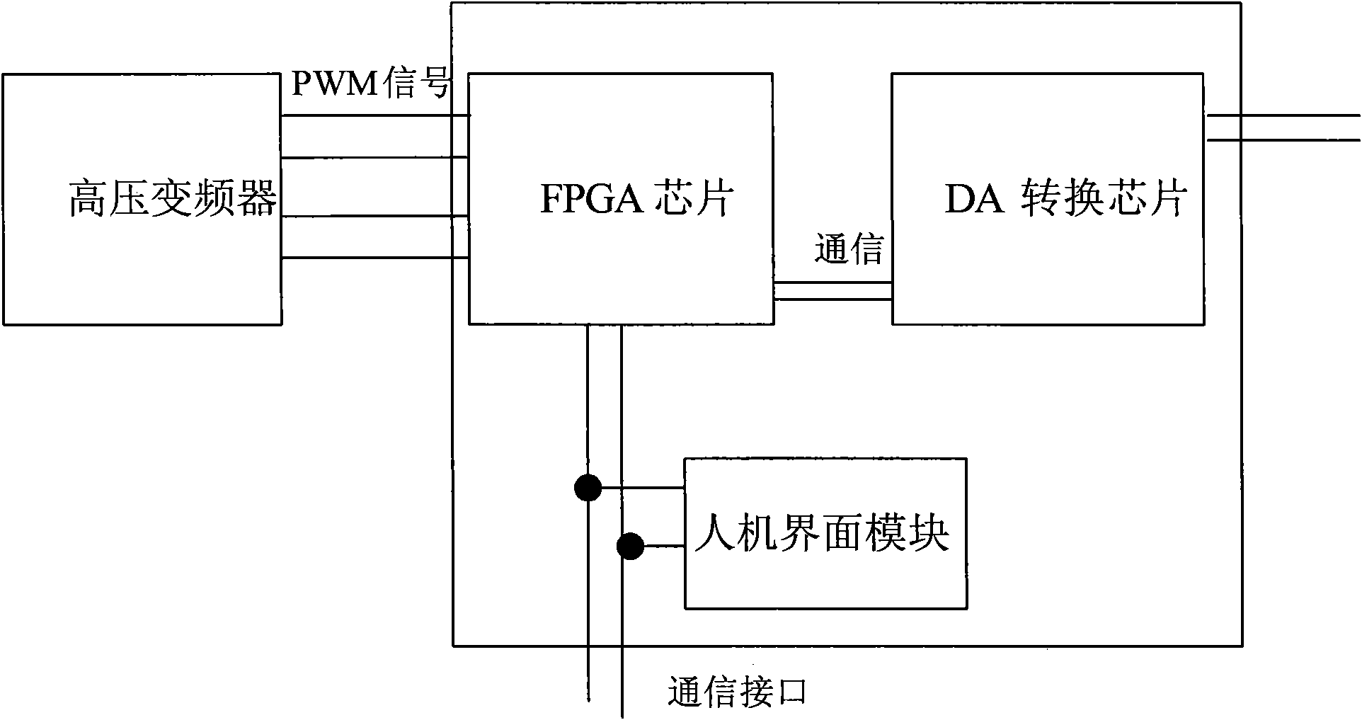
[0043]Such as figure 2 As shown, the present embodiment realizes the functions of the PWM detection module and the data processing module simultaneously by selecting a high-performance FPGA chip (the A3P030 type of the ProASIC3 series), and selects an industrial computer or an embedded system device with a display screen to realize the man-machine interface module. Function, choose DA conversion chip to realize the function of DA output interface. The FPGA chip detects the PWM wave output by the high-voltage inverter in real time and at high speed, and determines the superimposed value of each phase. The principle is the conduction relationship of the IGBT. Taking the PWM wave in the (3) stage as an example, the rules for detecting the PWM wave are shown in Table 2:
[0044] The PWM detection result of the (3) stage of Table 2
[0045] PWM_L
[0046] Therefore, if it is a five-cascade high-voltage inverter, through the PWM detection of each cascade, and then superi...
Embodiment 2
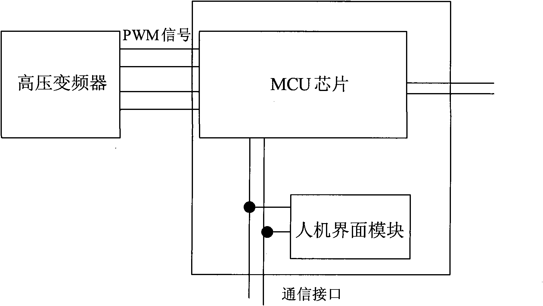
[0048] Such as image 3 As shown, this embodiment realizes the functions of the PWM detection module, the data processing module and the DA output interface by selecting an MCU chip (STM32F103RD type) with a DA output interface at the same time, and selects an industrial computer to realize the function of the man-machine interface module. The MCU chip detects the PWM wave output by the high-voltage inverter in real time and at high speed through the IO interrupt, and determines the superimposed value of each phase. The detection principle is the same as that of Embodiment 1; the MCU chip can conveniently calculate the output voltage frequency, effective value, etc. based on the PWM detection results; In addition, the MCU chip outputs the PWM detection results and other values in the form of voltage through the DA output interface, and the tester can read them through the oscilloscope; at the same time, the MCU chip can provide various communication interfaces such as RS232 i...
Embodiment 3
[0050] Such as Figure 4 As shown, this embodiment can combine the characteristics of fast detection signal of FPGA and strong data processing capability of MCU. The FPGA chip uses the A3P030 chip of the ProASIC3 series, which realizes the function of the PWM wave detection module, that is, it is used to be responsible for the PWM wave detection, and the detection results are passed through the parallel port and the I 2 C passes to MCU chip, and detection principle is the same as embodiment 1; 2 The C interface reads the PWM detection results transmitted by the FPGA chip, and calculates the voltage frequency, effective value, average value, etc. in real time; at the same time, the PWM detection results and other values are output in the form of voltage through the DA output interface, and the tester can use the oscilloscope In addition, the MCU chip can provide various communication interfaces such as RS232 interface, SPI interface or CAN interface, and realize communicatio...
PUM
 Abstract
Description
Claims
Application Information
 - R&D
- Intellectual Property
- Life Sciences
- Materials
- Tech Scout
- Unparalleled Data Quality
- Higher Quality Content
- 60% Fewer Hallucinations
Browse by: Latest US Patents, China's latest patents, Technical Efficacy Thesaurus, Application Domain, Technology Topic, Popular Technical Reports.
© 2025 PatSnap. All rights reserved.Legal|Privacy policy|Modern Slavery Act Transparency Statement|Sitemap|About US| Contact US: help@patsnap.com


