

Integrated filter inductance transformer
A technology for filtering inductors and transformers, applied in the field of transformers, can solve problems such as harmonic pollution, and achieve the effects of good filtering, cost reduction, and good harmonic magnetic flux suppression effect.
- Summary
- Abstract
- Description
- Claims
- Application Information
AI Technical Summary
Problems solved by technology
Method used
Image

Examples
Embodiment Construction
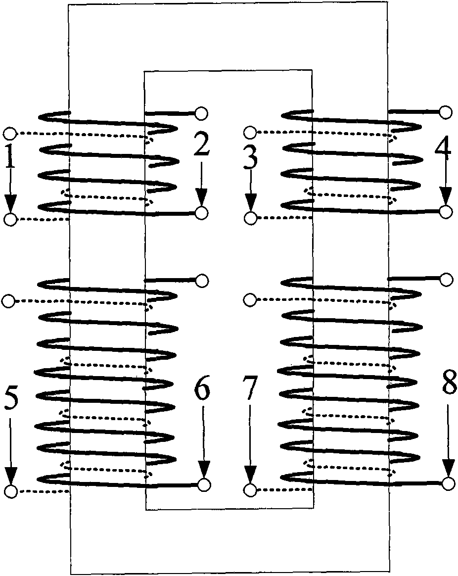
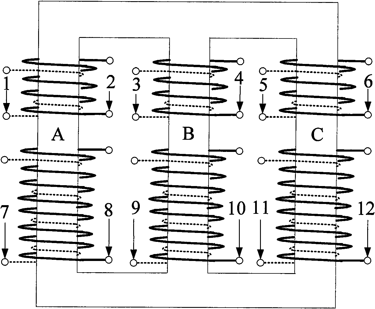
[0013] see figure 1 and figure 2 , figure 1 The schematic diagram of the structure of the winding of the LC resonant circuit integrating the 5th and 7th characteristic harmonics. figure 1 Among them, 6 and 8 are primary windings, 5 and 7 are secondary windings; 1 and 3 are 5 times integrated filter windings; 2 and 4 are 7 times integrated windings. figure 2 Among them, 8, 10, and 12 are primary windings, 7, 9, and 11 are secondary windings; 1, 3, and 5 are 5th integrated filter windings; 2, 4, and 6 are 7th integrated windings. The low-voltage winding of the transformer is placed close to the inner side of the iron core, the high-voltage winding is placed outside the low-voltage winding, and the 5th and 7th filter inductor windings are arranged on the same iron core as the high-voltage winding and the low-voltage winding. Each filter winding is two anti-parallel symmetrical interleaved windings. This kind of coil can be divided into some identical units in terms of leakag...
PUM
 Abstract
Description
Claims
Application Information