Low noise generator for frequency swept signals

A signal generator and signal generation technology, applied in the direction of instruments, utilization of re-radiation, specific array feeding systems, etc., can solve problems such as radar desensitization, improve signal strength, avoid near-carrier phase noise, and simplify filter layout Effect

Active Publication Date: 2009-12-09
QINETIQ LTD
View PDF3 Cites 10 Cited by
  • Summary
  • Abstract
  • Description
  • Claims
  • Application Information

AI Technical Summary

Problems solved by technology

However, phase noise on the LO output can cause the pro

Method used


Image

  • Low noise generator for frequency swept signals
  • Low noise generator for frequency swept signals
  • Low noise generator for frequency swept signals

Examples


Embodiment Construction

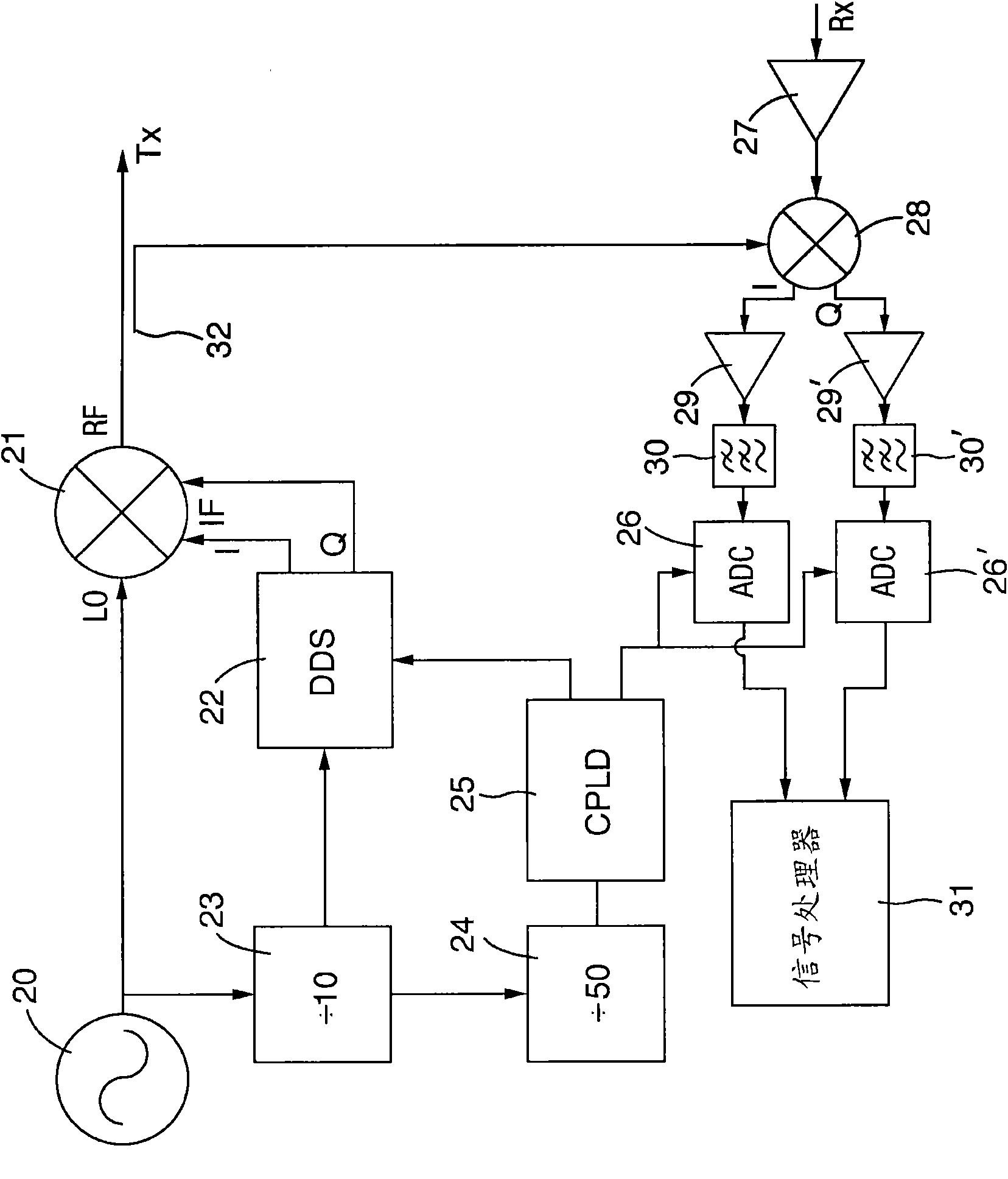
[0038] figure 2 The first embodiment of the present invention is shown. This figure shows part of a simplified block diagram of the FMCW radar system. The FRO used as a local oscillator (LO) 20 that is operable at 9.2 GHz is provided as an input to the quadrature up-conversion mixer 21. The second input of the mixer 21 comes from an IF oscillator in the form of a direct digital synthesizer (DDS) device 22, in this case the IF oscillator is implemented using a pair of analog device AD9858 DDS chips. In addition to providing the input to the mixer 21, the output of the LO 20 is also fed to the first frequency divider 23, which in turn drives the second frequency divider 24. The output of the first frequency divider 23 is used as the reference clock source of the direct digital synthesizer 22. The second frequency divider 24 provides a clock reference source to a complex programmable logic device (CPLD) 25, which has outputs connected to both the DDS and analog-to-digital converter...


PUM


Abstract

A signal generation system suitable for use in a radar system comprises a local oscillator (LO) and an intermediate frequency IF oscillator, wherein the IF oscillator is a Direct Digital Synthesiser, and the LO is a free runn ing oscillator not itself locked to another oscillator but which acts as a c lock reference for the DDS and is the highest frequency oscillator in the sy stem. The LO may also act as a reference for a receive chain digitiser. The invention exploits phase noise advantages of a free running oscillator at so me distance from the carrier whilst maintaining coherency with other system components. The system typically finds application in FMCW radars.

Description

Technical field [0001] The present invention relates to signal generation systems, such as those commonly used in radar systems. In particular, the present invention relates to radar systems, especially FMCW (Frequency Modulated Continuous Wave) radar systems, in which it is advantageous to keep the phase noise generated in key system components as low as possible in practice and economically to obtain improved operating performance . Background technique [0002] The FMCW radar system is characterized by having simultaneous transmitting and receiving functions. This may lead to problems that are not encountered in more traditional pulse radars. In more traditional pulse radars, the signal may often "leak" from the transmitter to the receiver via the corresponding antenna. The energy comes directly from the transmitter. It is difficult to detect the signal received from the target. This problem is improved by designing the transmitting and receiving antennas and related subsystem...

Claims


Application Information

Patent Timeline
IPC IPC(8): H03B23/00
CPCH03B23/00G01S7/352H01Q21/065H01Q21/0031G01S7/023H01Q1/3233H01Q25/008G01S7/0232G01S7/0236H01Q13/206G01S13/34
Inventor P·D·L·比斯利
Owner QINETIQ LTD
Why Eureka
Try Eureka