Method for sealing vacuum glass exhaust tube

A technology of vacuum glass and air extraction pipe, which is applied in glass forming, glass remolding, glass manufacturing equipment, etc. The effect of automating production operations, shortening the vacuuming time, and improving the vacuuming efficiency

Inactive Publication Date: 2009-12-16
左树森
View PDF0 Cites 7 Cited by
  • Summary
  • Abstract
  • Description
  • Claims
  • Application Information

AI Technical Summary

Problems solved by technology

All vacuum glass has an exhaust tube due to the manufacturing process, and the vacuum tube is used to connect the negative pressure generator to introduce negative pressure into each vacuum chamber, and then melt the exhaust tube for sealing. The sealing method of the tail tube is mainly Flame fusion sealing, electric fusion sealing and infrared lamp fusion sealing, etc., these methods have the following defects in common: 1. The vacuuming time is too long, the fusion sealing time is long, the fusion sealing efficiency is low, and the damage to the glass substrate is large. After melting, there will be a section of fused exhaust tailpipe, which is unsightly and easy to break, with a high breakage rate; 2. At least one exhaust tailpipe is left between adjacent glass substrates, and each exhaust tailpipe There are hidden dangers of air leakage in the pipes, and it is not convenient for handling and construction, resulting in an increase in the scrap rate; 3. The entire process is complicated, difficult to operate, and the consumables consume a lot of energy and cost a lot.
The JC / T1079-2008 vacuum glass industry standard that came into effect on December 1, 2008 also stipulates that the tailpipe should be sealed and protected. The above defects have seriously affected the wide use of vacuum glass and hindered the use of vacuum glass. Further development

Method used


Image

  • Method for sealing vacuum glass exhaust tube
  • Method for sealing vacuum glass exhaust tube
  • Method for sealing vacuum glass exhaust tube

Examples


Embodiment 1

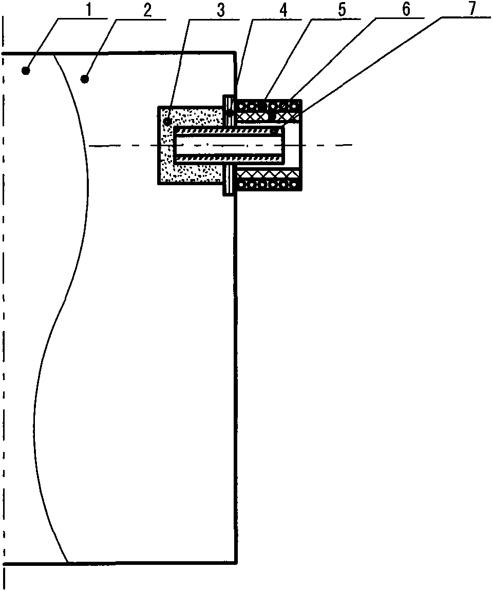
[0025] Embodiment 1: see figure 1 .

[0026] This embodiment belongs to the way of sealing the exhaust pipe in the vacuum heating furnace.

[0027] The top glass 1 and the base glass 2 form a double-layer vacuum glass, and a groove 3 is made on the edge between the top glass and the base glass, and a suction pipe 7 is placed in the groove, and the suction pipe is generally used It is advisable to use glass tubes, or other materials that can be matched with flat glass, arrange low-melting point glass powder around the suction pipe in the groove; an induction medium 6 is coaxially set on the suction pipe outside the substrate glass, and the induction medium It can be made of iron, chromium, cadmium, nickel, tungsten, and carbon-containing materials that generate induced current in an alternating magnetic field. Disc or multi-lobed, etc. Leave a gap of 0-5mm between the sensing medium and the substrate glass, or place a thermal insulation layer 4 such as a mica sheet in the ga...

Embodiment 2

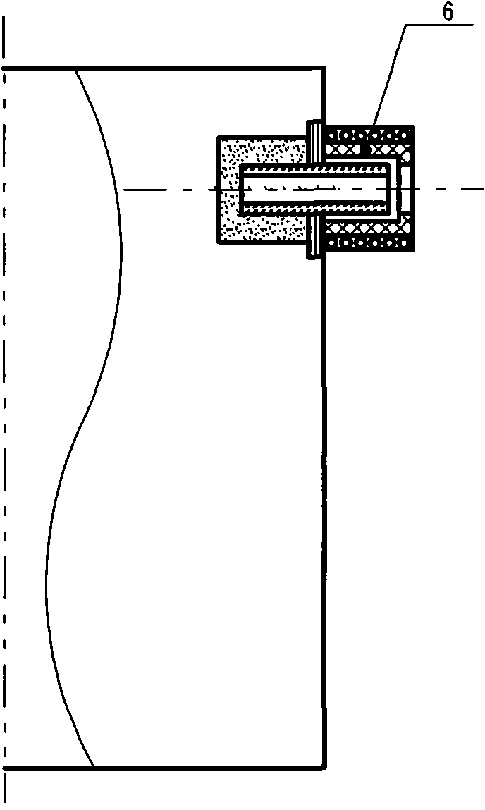
[0030] Example 2: see figure 2 .

[0031] The outer end of the induction medium is made into a constricted shape, and the others are the same as in Embodiment 1.

Embodiment 3

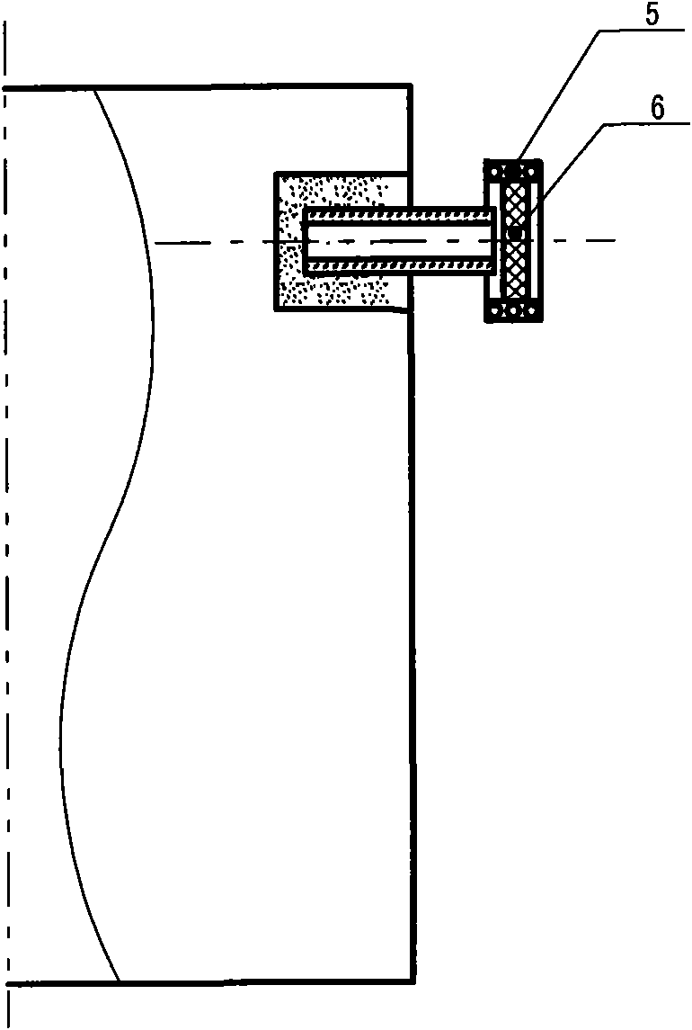
[0032] Embodiment 3: see image 3 .

[0033] The induction medium is made into a disc shape, placed on the front end of the exhaust pipe, and the induction coil is installed on the radial periphery of the induction medium. This structure can omit the heat insulation layer. Others are the same as in Example 1.


PUM


Abstract

The invention relates to a method for sealing a vacuum glass exhaust tube. The exhaust tube outside a base glass is provided with an induction medium, a gap of 0 to 5 millimeters is reserved between the induction medium and the end face of the base glass, an induction coil is arranged outside the induction medium, the induction coil is connected with a variable frequency induction device and heats the induction medium, and the induction medium finishes sealing the exhaust tube by heating and melting the exhaust tube through radiant heat. By using a variable frequency induction heating mode to heat and seal the exhaust tube, a tail tube of the exhaust tube is parallel to or lower than the base glass, the plain-end tailless sealing of the exhaust tube is realized, the vacuum glass is convenient to transport and mount and has attractive appearance, and the breakage rate is reduced; and the method is suitable for automatic production and operation, solves the unsolved problems up to now at home and abroad, and contributes to the vacuum glass industry.

Description

technical field [0001] The invention belongs to the field of vacuum glass, in particular to a sealing method for a vacuum glass suction pipe. Background technique [0002] The sound insulation, heat insulation and thermal insulation properties of vacuum glass are much better than ordinary glass and laminated glass, and its application prospect is very broad. The manufacture and application of vacuum glass has a history of ten years. So far, only Japan Sheet Glass Company, China Xinliji Company and Qingdao Hengda Company have achieved large-scale production. All vacuum glass has an exhaust tube due to the manufacturing process, and the vacuum tube is used to connect the negative pressure generator to introduce negative pressure into each vacuum chamber, and then melt the exhaust tube for sealing. The sealing method of the tail tube is mainly Flame fusion sealing, electric fusion sealing and infrared lamp fusion sealing, etc., these methods have the following defects in commo...

Claims


Application Information

Patent Timeline
Patent Type & Authority Applications(China)
IPC IPC(8): C03B23/057C03C27/06
Inventor 左树森
Owner 左树森
Why Eureka
Try Eureka