Process for treating top gas of reduction shaft furnace

A furnace top gas and treatment process technology, applied in the field of metallurgical chemistry, can solve the problems of energy consumption, water consumption, increased investment, excessive waste gas, and slow heating speed of hot blast stoves, so as to reduce investment costs and operating energy consumption. The effect of improving energy consumption and saving coal consumption

Active Publication Date: 2009-12-16
CISDI ENG CO LTD
View PDF0 Cites 9 Cited by
  • Summary
  • Abstract
  • Description
  • Claims
  • Application Information

AI Technical Summary

Problems solved by technology

The key of the SDRF gas process is to use the method of recirculation of the top gas of the reduction shaft furnace to completely recover the heat of the gas at the outlet of the smelting gas furnace, and to use dry dust removal for the top gas of the reduction shaft furnace. The lack of consideration of heat and pressure energy recovery of the furnace top gas is mainly reflected in the following points: 1) The gas outlet of the reduction shaft furnace top has a relatively high temperature, and it needs to be cooled before entering the dry dust removal process, which was not considered in the original process The heat energy recovery of this part of the gas cooling: 2) The original process uses the gas tank to regulate the pressure fluctuation of the pipe network. The storage pressure of the gas tank is low, so that the gas needs to be expanded and depressurized before entering the gas tank. After expansion, it enters the decarbonization system. out of CO 2 It needs to increase the pressure and lower the temperature to meet the entry temperature and pressure requirements of the decarbonization system. Such a treatment process leads to an increase in energy consumption, water consumption and investment, and does not make full use of the pressure of the reduction shaft furnace top gas itself; 3) the original The process uses a hot blast stove to heat part of the reducing gas entering the reduction shaft furnace. The heating speed of the hot blast stove is slow, the investment is high, and the waste gas emitted by heating is more

Method used


Image

  • Process for treating top gas of reduction shaft furnace

Examples


Embodiment Construction

[0023] An embodiment of the present invention will be further described below in conjunction with accompanying drawing:

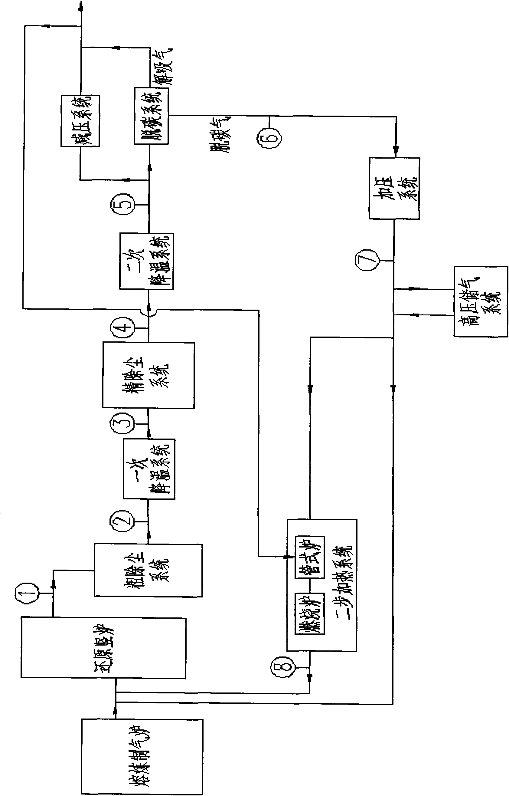
[0024] The process includes 8 sub-process systems, namely: 1) coarse dust removal system; 2) primary cooling system; 3) fine dust removal system; 4) secondary cooling system; 5) decarburization system and decompression system; 6) pressurization system; 7) high-pressure gas storage system; 8) two-step heating system. The above-mentioned 8 process systems are connected together through transmission pipelines and transmission devices, and finally the gas with high reduction degree is sent to the direct reduction furnace.

[0025] The system flow is as follows:

[0026] Reduction shaft furnace top gas ① first passes through a coarse dust removal system such as a hot cyclone dust collector for rough dust removal, and then the gas ② enters a primary cooling system such as a heat pipe heat exchanger for heat energy recovery. The by-product is medium-pressure stea...


PUM


Abstract

The invention belongs to the metallurgical chemical technology, and relates to a process for treating top gas of a reduction shaft furnace. The treatment process is characterized in that after the top gas exhausted from the reduction shaft furnace is subjected to dust removal and cooling treatment, the top gas enters a carbon removal system to remove CO2 in the gas; and one part of the carbon removal gas after carbon removal and compression is directly mixed with the high-temperature gas exhausted from a smelting gas-making furnace to enter the reduction shaft furnace, and the other part of the carbon removal gas is heated and then enters the reduction shaft furnace. The process for treating the top gas of the reduction shaft furnace has the advantages of reasonable flow, optimized energy conservation and discharge reduction and technical domestication, and can be used for an iron-making process of an SDRF furnace.

Description

technical field [0001] The invention belongs to the metallurgical chemical technology category, and relates to a reduction shaft furnace top gas treatment process, in particular to a reduction shaft furnace top gas treatment process for an SDRF furnace ironmaking process. technical background [0002] The SDRF furnace ironmaking process is a new type of ironmaking technology developed by China Metallurgical Saidi Engineering Technology Co., Ltd. It consists of a smelting gas furnace, a reduction shaft furnace, and a gas treatment system. The SDRF furnace is a production of hot metal. It also produces sponge iron, and a new ironmaking process suitable for gas output that is environmentally friendly, energy-saving, and water-saving. [0003] The SDRF furnace ironmaking process involves major issues such as gas backflow at the top of the reduction shaft furnace, gas heat energy, and pressure energy recovery. The gas process is a key component of the entire process. The key of ...

Claims


Application Information

Patent Timeline
Patent Type & Authority Applications(China)
IPC IPC(8): C21B11/02C21B13/02
CPCY02P10/122
Inventor 郭敏李佳楣陈凌彭华国王怀淳张涛
Owner CISDI ENG CO LTD
Why Eureka
Try Eureka