
Stirrer for desulphurization of molten iron

A technology of molten iron desulfurization and agitator, which is applied in the field of agitators, can solve the problems such as being unfavorable for being involved in the discharge of desulfurization slag, high eddy current intensity at the lower part of the back iron surface of the stirring blade, and deterioration of the dynamic conditions of stirring and desulfurization.

Active Publication Date: 2009-12-16
武汉钢铁有限公司 +1
View PDF3 Cites 45 Cited by
  • Summary
  • Abstract
  • Description
  • Claims
  • Application Information

AI Technical Summary

Problems solved by technology

In addition, in view of the lack of low entrainment strength of the conventional agitator with a small-angle inclined iron surface, from the perspective of strengthening the agitator's agitation strength, the Chinese patent "A Stirring Head for Molten Iron Desulfurization" ZL200720084348.9 discloses a stirring impeller The iron surface is a front concave arc surface, the back iron surface is an upper concave and lower convex multi-segment arc surface, and the side is a molten iron desulfurization agitator with an inclined surface from bottom to top. Through the special-shaped structure of the stirring blade, it can improve the impact of the stirring head on the desulfurization agent. The purpose of stirring entrainment strength and improving desulfurization kinetic conditions
However, the above-mentioned patents and conventionally used agitators are arranged in a four-blade cross shape, and the angle between the agitating blades is 90°, which provides convenience for the sticky slag between the agitating blades. The interference effect of the impeller leads to a large vortex intensity at the lower part of the back iron surface of the stirring blade, which is not conducive to the discharge of the desulfurization slag involved and deteriorates the dynamic conditions of the stirring desulfurization

Method used


Image

  • Stirrer for desulphurization of molten iron
  • Stirrer for desulphurization of molten iron
  • Stirrer for desulphurization of molten iron

Examples


Embodiment Construction

[0012] Describe in further detail below in conjunction with accompanying drawing:

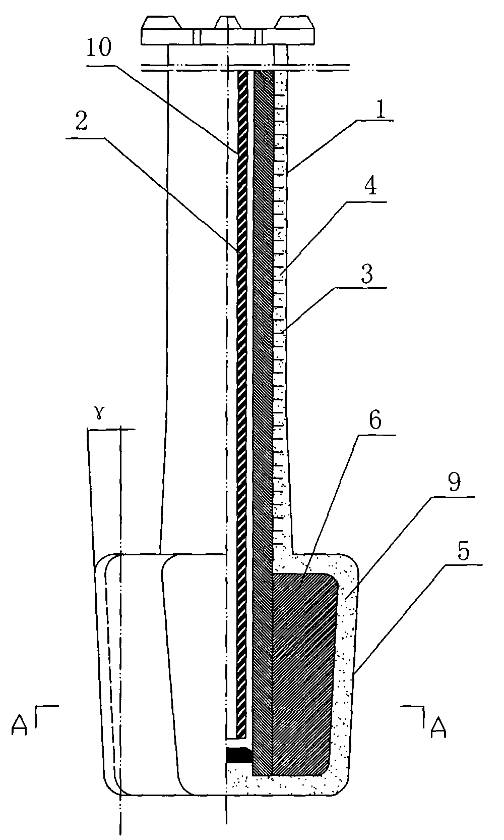
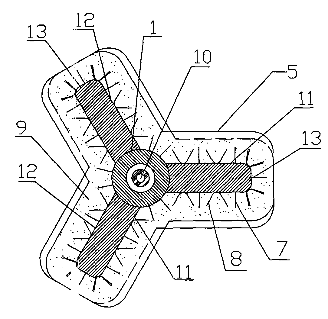
[0013] A new type of stirring head for molten iron desulfurization, which consists of a metal core 2 forming a rotating shaft 1, a V-shaped rivet 3, a refractory lining 4, and a metal chip 6 forming a stirring blade 5, a V-shaped rivet 7, and double V-shaped rivets 8. Composed of refractory lining 9 and air-cooled pipe 10. The stirring blade 5 consists of three pieces.

[0014] In the following embodiments, the air-cooled pipe 10 is made of No. 15 seamless steel pipe; the metal core 2 is made of 20CrMo or 30CrMo thick-walled cast steel pipe; V-shaped rivets 3, V-shaped rivets 7 and double V-shaped rivets 8 The height is 1 / 2 to 2 / 3 of the thickness of the refractory working lining. Among them, the V-shaped riveting member 3 is made of ordinary wire rod with a diameter of 8mm, and the V-shaped riveting member 7 is made of outer rib steel bar with a diameter of 10mm, double V-shaped rivets 8 are...


PUM


Abstract

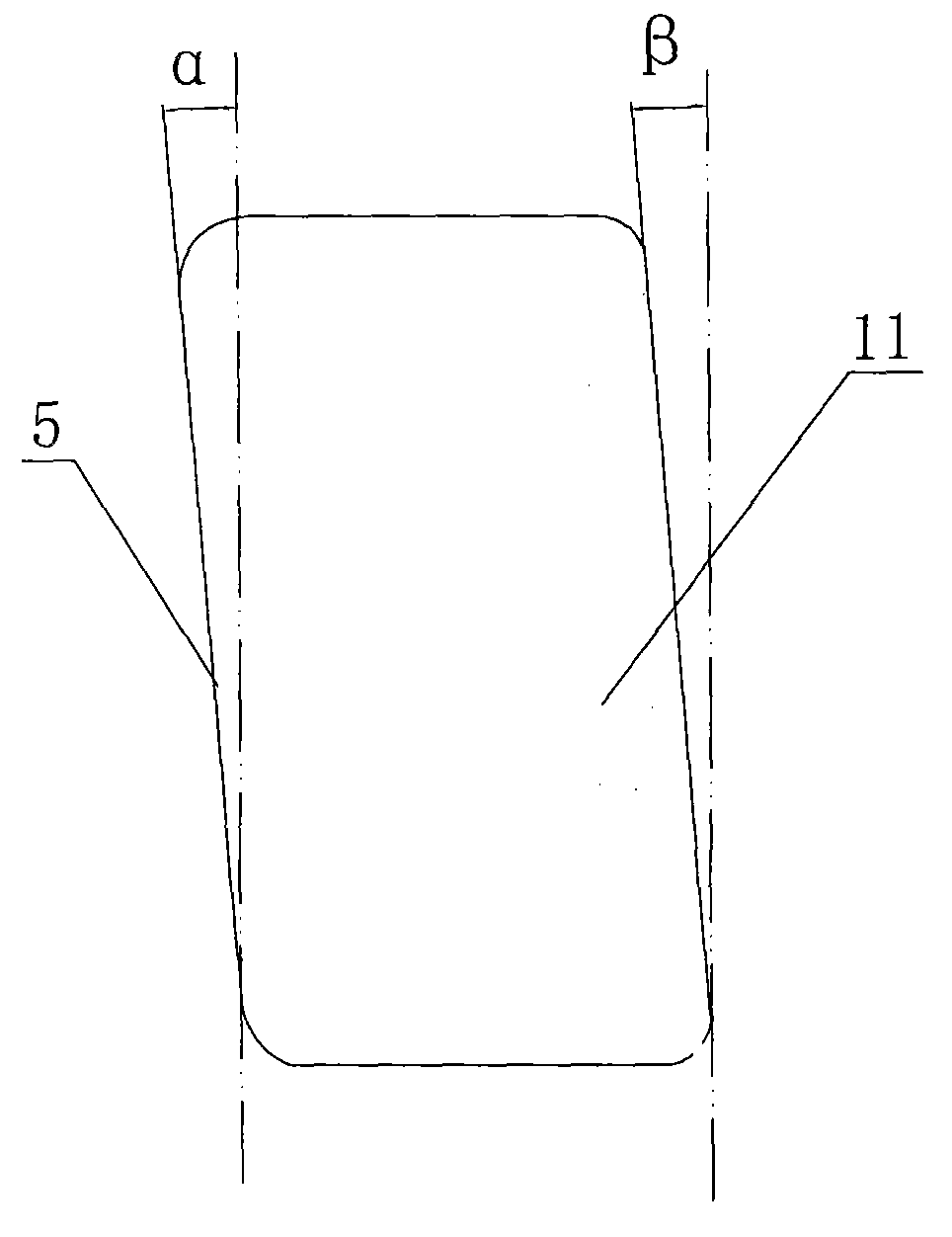
The invention relates to a stirrer for external stirring desulphurization of molten iron before converter steelmaking, aiming at solving the existing deficiencies at present that slags among mixing blades are numerous, large intensity of vortex at the bottom of the metal opposing side of the mixing blades is disadvantageous to the discharging of the involved desulphurization slags. The invention comprises the following measures: the stirrer for desulphurization of molten iron is composed of a metal core 2, a V-shaped rivet firmware 3, a refractory liner 4, a metal chip 6, a V-shaped rivet firmware 7, a double V-shaped rivet firmware 8, a refractory liner 9 and an air cooling tube 10; the metal core 2, the V-shaped rivet firmware 3 and the refractory liner 4 constitute a rotation axis 1; the metal chip 6, the V-shaped rivet firmware 7, the double V-shaped rivet firmware 8, the refractory liner 9 and the air cooling tube 10 constitute mixing blades 5; three mixing blades 5 above the rotation axis 1 are evenly distributed; the front rake angle alpha of the inclined plane from bottom to top of the metal facing water surfaces 11 of the mixing blades 5 is 4.1-30 degrees, the front rake angle beta of the inclined plane from bottom to top of the metal opposing surfaces 12 is 0.1-30 degrees, the camber angle gamma of the inclined plane from bottom to top of the outside surface 13 is 4.1-15 degrees. In the invention, slags among the mixing blades are small, the dynamic condition for stirring desulphurization is excellent, the service life is long and the structure is simple.

Description

technical field [0001] The invention relates to a stirrer for stirring desulfurization outside a molten iron furnace before converter steelmaking, in particular to a stirrer for pretreatment of a KR stirring desulfurization of a molten iron tank. Background technique [0002] KR (Kambara Reactor) stirring desulfurization method is a desulfurization technology outside the molten iron furnace that Nippon Steel of Japan began to study in 1963 and applied to industrial production in 1965. This desulfurization method is to immerse a stirring head lined with refractory material into molten iron The tank rotates and stirs the molten iron to create a vortex. The weighed desulfurizer is added to the surface of the molten iron by the feeder and is drawn into the molten iron by the vortex. It mixes and reacts with the high-temperature molten iron to achieve the purpose of desulfurization. The desulfurization method has the characteristics of high desulfurization efficiency, less desulf...

Claims


Application Information

Patent Timeline
IPC IPC(8): C21C1/02
Inventor 欧阳德刚刘守堂李具中蒋扬虎吴杰夏春祥田义胜罗安智王海清李明辉罗巍朱善合杨超胡清明
Owner 武汉钢铁有限公司
Learn More