Oscillating damper

A shock absorber and outer cylinder technology, applied in the field of machinery, can solve the problems of difficult installation, inconvenient replacement and maintenance, and difficult manufacturing of external circulation oil pipes, and achieve easy stepless linear adjustment, improved convenience, and cost-effectiveness. The effect of low production cost

Inactive Publication Date: 2009-12-16
浙江中兴减震器制造有限公司
View PDF2 Cites 7 Cited by
  • Summary
  • Abstract
  • Description
  • Claims
  • Application Information

AI Technical Summary

Problems solved by technology

[0005] Although the above solution can effectively improve the working performance of the shock absorber, it is difficult to process and manufacture, especially the installation of the external circulation oil pipe is relatively difficult, and it is easy to be scrapped during the manufacturing process, and the yield is low
Moreover, it is prone to damage during use, and it is not convenient enough to replace and repair
On the other hand, the cost of processing and manufacturing is also high, and the economy is poor

Method used


Image

  • Oscillating damper
  • Oscillating damper

Examples


Embodiment 1

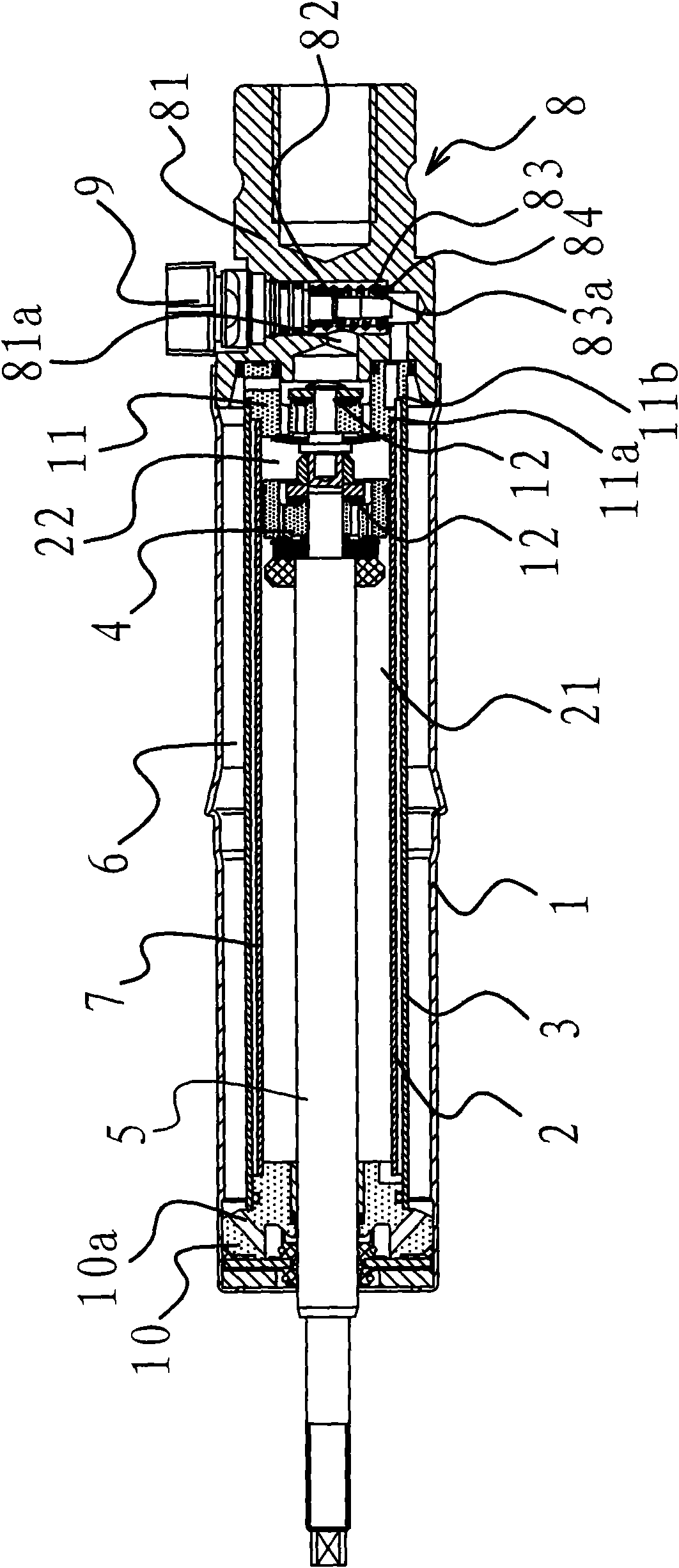
[0024] Such as figure 1 As shown, the shock absorber includes parts such as an outer cylinder 1, a cylinder 2, an intermediate cylinder 3, a piston 4, a piston rod 5, a regulating valve 8, and a guide 10.

[0025] The cylinder 2 is arranged in the outer cylinder 1, and the outer cylinder 1 is also provided with an intermediate cylinder 3 which is sleeved outside the cylinder 2. There is an annular cavity 6 between the outer cylinder 1 and the intermediate cylinder 3. In the middle There is an annular chamber 2 7 between the barrel body 3 and the cylinder barrel 2 . The cylinder 2 is provided with a piston 4 and a piston rod 5 fixedly connected with the piston 4 , the piston 4 divides the cylinder 2 into an upper chamber 21 and a lower chamber 22 , and the outer end of the piston rod 5 extends out of the outer cylinder 1 . A regulating valve 8 is provided at the bottom of the outer cylinder 1 . The piston rod 5 in this embodiment is thinner.

[0026] In this embodiment, the ...

Embodiment 2

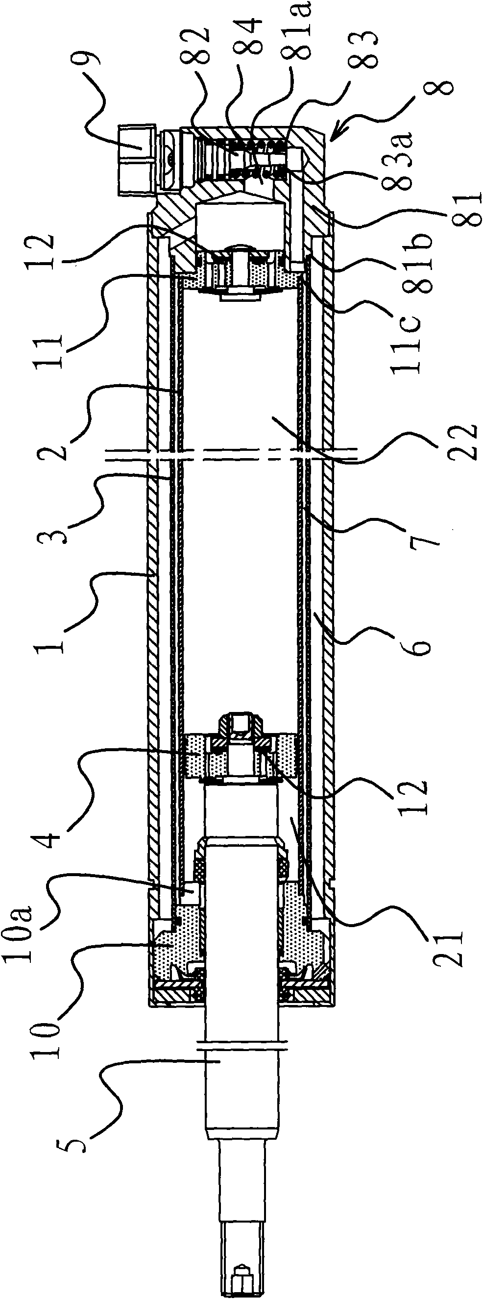
[0030] Such as figure 2 As shown, in this embodiment, the compression valve seat 11 is provided with an annular step 3 11c, the regulating valve 81 is provided with an annular step 4 81b, one end of the cylinder 2 is against the annular step 3 11c, and the middle cylinder One end of the body 3 leans against the annular step 4 81b. The piston rod 5 in this embodiment is relatively thick. The rest are similar to those in Example 1, and will not be described in detail herein.

Embodiment 3

[0032] In this embodiment, the first annular chamber 6 is an oil circulation chamber, and the second annular chamber 7 is an oil storage chamber. Since the positions of the oil storage chamber and the oil circulation chamber in this implementation are different from those in Embodiment 1 and Embodiment 2, the structure of the rest of the shock absorber, such as guides, regulating valves, and compression valves, should also be adjusted accordingly. The rest are similar to Embodiment 1 or Embodiment 2, and will not be described in detail herein.


PUM


Abstract

The invention provides an oscillating damper and belongs to the technical field of machinery. The oscillating damper solves the problems that the prior oscillating damper is inconvenient to mount and detach and has a complex machining process, low finished product rate, high product cost, unstable working performance, single damp adjusting mode and the like. The oscillating damper comprises an outer cylinder body and a cylinder; the inside of the cylinder is provided with a piston and a piston rod; the cylinder is divided into an upper cavity and a lower cavity by the cylinder; the outer end of the piston rod extends out of the outer cylinder body; the inside of the outer cylinder body is also provided with a middle cylinder body sleeved outside the cylinder; an annular cavity 1 is arranged between the outer cylinder body and the middle cylinder body; an annular cavity 2 is arranged between the middle cylinder body and the cylinder; one of the annular cavity 1 and the annular cavity 2 is an oil storage cavity, and the other one is an oil circulating cavity; the upper cavity and the lower cavity are communicated with the oil circulating cavity respectively; and the lower cavity is communicated with the oil storage cavity. The oscillating damper has the advantages of convenient mounting and detachment, simple machining process, high finished product rate, low product cost, high working stability, diverse damp adjusting modes and the like.

Description

technical field [0001] The invention relates to the technical field of machinery, in particular to a shock absorber. Background technique [0002] As people's requirements for the comfort and stability of vehicles are getting higher and higher, people have designed various vehicle damping devices. The shock absorber is arranged between the vehicle frame and the axle, and the piston in the shock absorber moves up and down, and the oil in the shock absorber cavity repeatedly flows from one cavity through different pores into another cavity. At this time, the friction between the hole wall and the oil and the internal friction between the oil molecules form a damping force on the vibration, so that the vehicle vibration energy is converted into oil heat energy, which is then absorbed by the shock absorber and released into the atmosphere. [0003] In order to solve the problem of improving the working performance of the shock absorber, people have carried out long-term explora...

Claims


Application Information

Patent Timeline
Patent Type & Authority Applications(China)
IPC IPC(8): F16F9/19F16F9/32F16F9/34F16F9/36
Inventor 李宏曹志文周秀娟
Owner 浙江中兴减震器制造有限公司
Why Eureka
Try Eureka