Compact type self-resonant diaphragm filter

A self-resonant, compact technology, applied to waveguide devices, electrical components, circuits, etc., can solve the problems of difficult to reduce the center frequency of the passband, difficult to realize narrow-band filters, etc., and achieve volume reduction and good out-of-band suppression Effect

Inactive Publication Date: 2009-12-16
成都赛纳赛德科技有限公司
View PDF0 Cites 4 Cited by
  • Summary
  • Abstract
  • Description
  • Claims
  • Application Information

AI Technical Summary

Problems solved by technology

Compared with the direct coupling cavity filter, the length is shortened to one-half. However, due to the strong coupling between the self-resonant diaphragm and the connecting waveguide, it is difficult to realiz

Method used


Image

  • Compact type self-resonant diaphragm filter
  • Compact type self-resonant diaphragm filter
  • Compact type self-resonant diaphragm filter

Examples


Embodiment 1

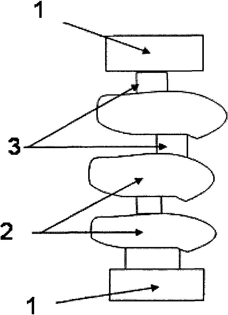
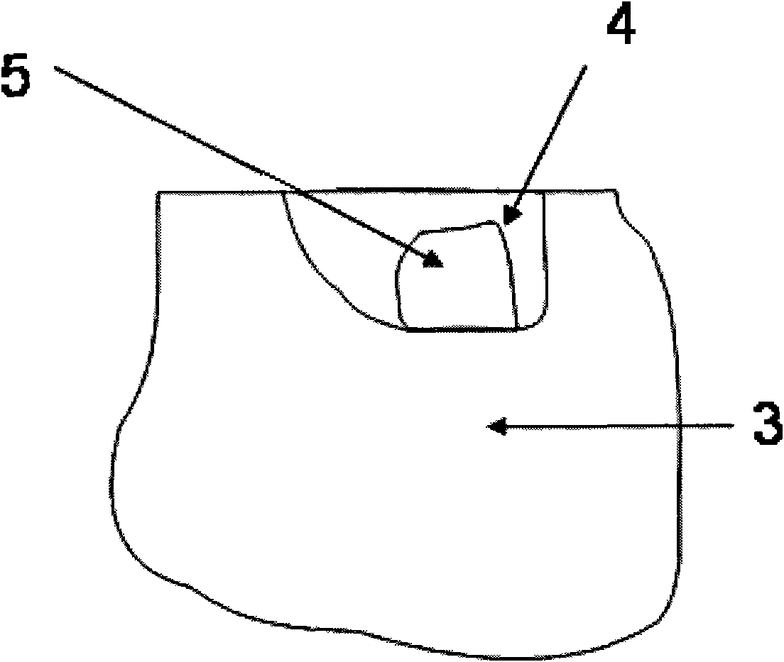
[0029] Such as figure 1 , figure 2 As shown, the compact self-resonant diaphragm filter is composed of an input-output structure 1, a resonant cavity 2 and a self-resonant diaphragm 3, and a coupling hole 4 communicating with the resonant cavity 2 is provided on the self-resonant diaphragm 3; the coupling hole 4 is provided with at least one metal boss 5 inside, and the bottom of the metal boss 5 is connected with the bottom of the coupling hole 4 . The upper surface of the coupling hole 4 is located in the same plane as the upper surface of the resonant cavity 2, and its lower surface is not in the same plane as the lower surface of the resonant cavity 2; At least one pair of side faces on the right side is not in the same plane; the length of the resonant cavity 2 along the filter axis is 0.1 mm smaller than one-fifth of the waveguide wavelength determined by the width of the resonant cavity at the highest frequency of the passband of the filter.

[0030] The resonant cav...

Embodiment 2

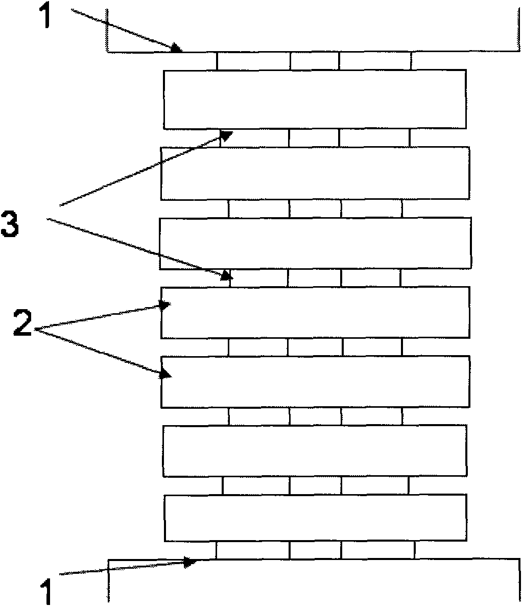
[0032] The difference between this embodiment and Embodiment 1 is that a self-resonant diaphragm 3 is provided between two adjacent resonant cavities 2 in this embodiment, and a self-resonant membrane is also provided between the resonant cavity 2 and the input-output structure 1. Sheet 3, and resonant cavity 2, self-resonant diaphragm 3, coupling hole 4 and metal boss 5 are all rectangular.

[0033] Based on embodiment 2, the tables of three different structural parameters are enumerated below, and correspondingly obtained as attached Figure 5 , attached Figure 6 , attached Figure 7 The scattering matrix curve is shown.

[0034] variable

size

(mm)

variable description

variable

size

(mm)

variable description

a0

22.9

Input and output port width

h1=h8

9.7

The height of the 1st and 8th coupling holes

b0

10.2

Input and output port height

h2=h7

9.8

The heigh...


PUM


Abstract

The invention discloses a compact type self-resonant diaphragm filter, which comprises an input structure and an output structure, a resonant cavity and a self-resonant diaphragm; the self-resonant diaphragm is provided with at least a coupling hole which is communicated with the resonant cavity, the coupling hole is internally provided with at least a metal boss which is connected with other metal parts only at the bottom of the coupling hole. The upper surface of the resonant cavity and the upper surface of the coupling hole are positioned at a same flat surface, while the lower surfaces thereof are not at the same flat surface. The invention has the advantages of simple structure, small volume, good out-band rejection, wide application range, wide range of work frequency under a certain width of the filter, meanwhile, the invention can also reduce processing difficulty of the filter, is widely applied to an electronic system with varying microwave wave bands, and is especially applied to military and civil fields such as radar, missile guidance, communication and the like.

Description

technical field [0001] The invention relates to a compact filter, in particular to a compact self-resonant diaphragm filter. It can be widely used in electronic systems in various microwave bands, especially in military and civilian fields such as radar, missile guidance, and communication. Background technique [0002] Modern microwave communications, especially satellite communications and mobile communications, require very high filter selectivity. Traditional filters generally obtain better selectivity by increasing the order of the filter, such as Buettwrorth and Chebyshev filters. The weight and volume of the filter obtained in this way are very large, which cannot meet the needs of modern communication. Although the elliptic function filter has good selectivity, it is difficult to realize. Therefore, how to obtain better selectivity without increasing the order of the filter, and at the same time, it is very meaningful to realize it easily. In this way of thinking...

Claims


Application Information

Patent Timeline
IPC IPC(8): H01P1/208
Inventor 王清源陈立峰
Owner 成都赛纳赛德科技有限公司
Why Eureka
Try Eureka