Optical engine

An optical engine, engine technology, applied in the direction of engine components, machines/engines, mechanical equipment, etc., can solve the problems of uneven movement, restricted, restricted observation, etc., achieve good self-lubricating effect, reduce weight, and avoid adverse effects Effect

Active Publication Date: 2012-03-07
CHERY AUTOMOBILE CO LTD
View PDF0 Cites 0 Cited by
  • Summary
  • Abstract
  • Description
  • Claims
  • Application Information

AI Technical Summary

Problems solved by technology

[0004] (1) In the prior art, the transparent piston is adopted, and its observation is limited;
[0005] (2) Using a short transparent cylinder liner, the uneven movement is easy to cause damage and the observation is also limited

Method used


Image

  • Optical engine
  • Optical engine
  • Optical engine

Examples


Embodiment Construction

[0031] The present invention will be described in detail below according to the accompanying drawings, which is a preferred embodiment among various implementations of the present invention.

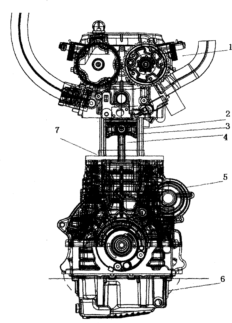
[0032] Such as figure 1 As shown, the optical engine is mainly modified on the multi-cylinder prototype. During the transformation process on the multi-cylinder prototype, the original engine cylinder head system, cylinder block, crankcase system, piston and other parts are kept unchanged. A transparent quartz glass cylinder liner is added between the cylinder block and the cylinder head, and the connection is fixed with bolts. The maximum operating speed of the modified optical engine is 2000r / min. It is mainly used to study the flow field in the engine cylinder, the formation of spray and mixed gas, etc. No research on in-cylinder combustion. The prototype piston is used to keep the shape of the top surface of the piston unchanged, so that the compression ratio of the optical engine c...


PUM


Abstract

The invention relates to an optical engine, wherein a transparent cylinder sleeve is arranged between a cylinder body and a cylinder cover of the engine, a piston is the original piston of the engine, and the length of the transparent cylinder sleeve is greater than the stroke of the engine. The invention specifically provides the optical engine which is based on rapid transformation of a multi-cylinder prototype machine and is applicable to researching the formation of a flow field, spray and mixed gas in the cylinder of the engine, in particular to researching the formation of the mixed gasof the optimized engine and a direct-injection engine in the cylinder.

Description

technical field [0001] The invention relates to the field of engines, in particular to an optical engine. Background technique [0002] At present, there are few optical engines in China, which are mainly used to study the combustion situation in the cylinder. According to the position of the transparent window, there are mainly two types. One type uses a transparent piston. Due to the fixed problem of the transparent piston, the transparent piston can only be as large as possible. Therefore, in this way, the optical engine can only see part of the flow field in the combustion chamber or combustion. The other type is based on the use of transparent pistons, adding a very short transparent quartz cylinder liner, because the transparent quartz glass cylinder liner is very easy to be scratched by the general piston ring, and it is very difficult for the piston ring to move between two different media. Ensuring smooth movement is also easy to damage the piston ring or the opti...

Claims


Application Information

Patent Timeline
Patent Type & Authority Patents(China)
IPC IPC(8): F02B77/00F02F1/00F02F5/00F01M13/00
Inventor 魏建城
Owner CHERY AUTOMOBILE CO LTD
Why Eureka
Try Eureka