Precompression device for polymer compression spring

A compression spring and polymer technology, applied in the field of pre-compression devices for polymer compression springs, can solve the problems of instability, machining, and poor uniformity of finished products, and achieve the effects of uniform shape, improved production efficiency, and convenient replacement

Inactive Publication Date: 2012-05-02
北京隆轩橡塑有限公司
View PDF8 Cites 0 Cited by
  • Summary
  • Abstract
  • Description
  • Claims
  • Application Information

AI Technical Summary

Problems solved by technology

[0004] In view of the above problems, the object of the present invention is to provide a pre-compression device for polymer compression springs that can overcome problems such as instability caused by the pre-compression of polymer compression springs, poor uniformity of finished products, and subsequent need for machining

Method used


Image

  • Precompression device for polymer compression spring
  • Precompression device for polymer compression spring
  • Precompression device for polymer compression spring

Examples


Embodiment 1

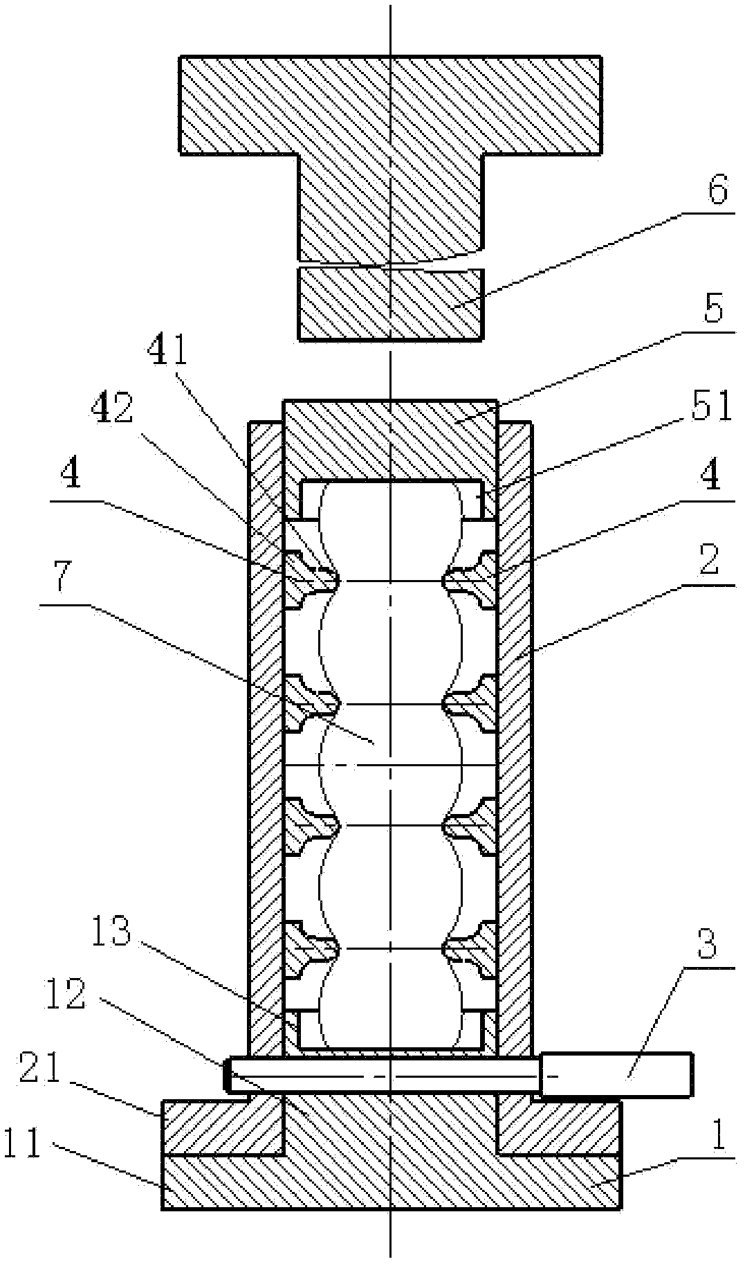
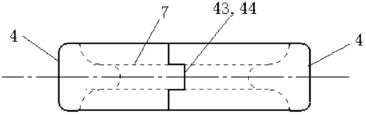
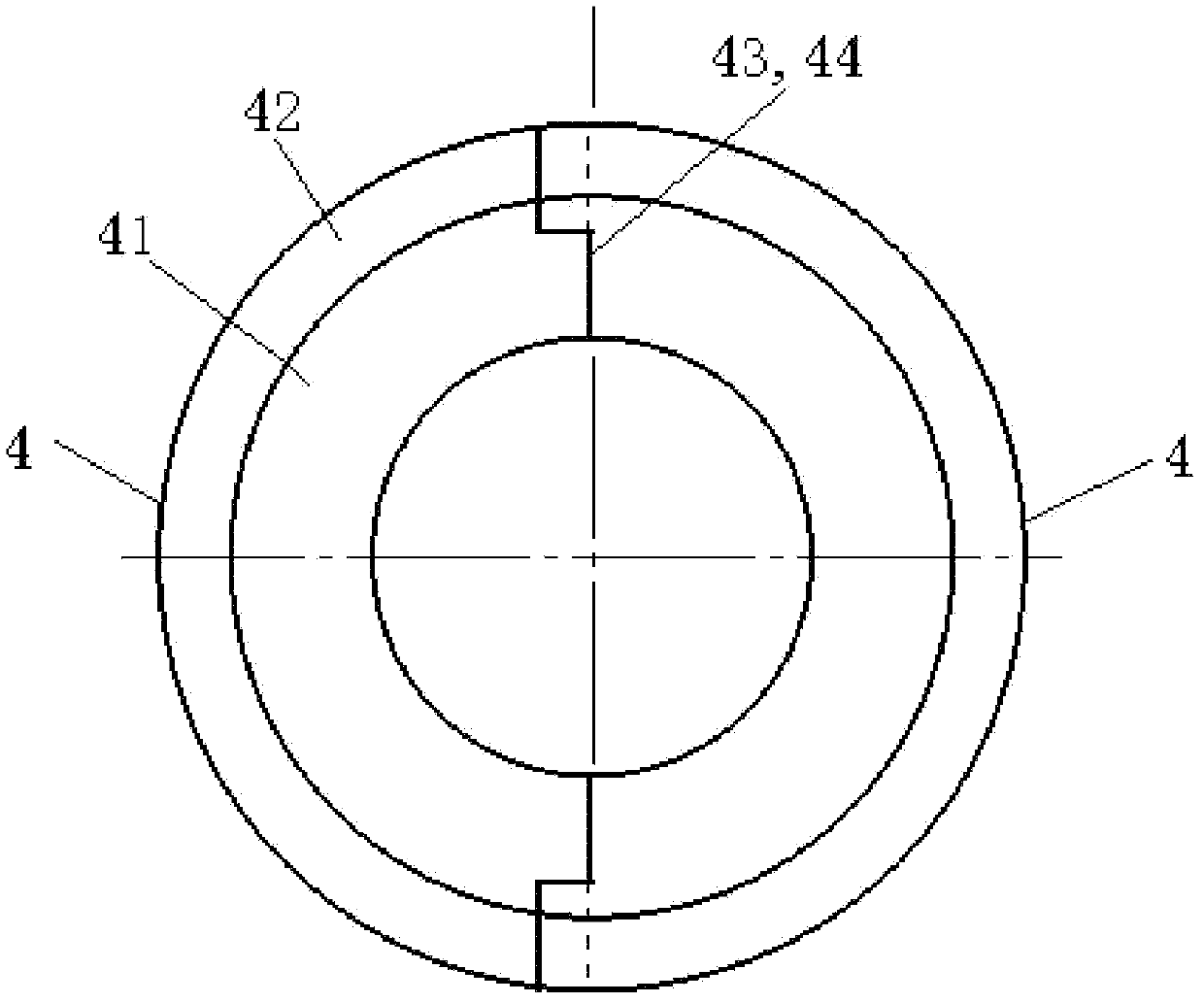
[0026] Embodiment one: if figure 2 , image 3 As shown, the positioning sleeve 4 is in a semi-circular shape as a whole, and the cross-section of the positioning sleeve 4 is in the shape of a "convex" laid down, that is, the positioning sleeve 4 includes an inner ring 41 and an outer ring 42, and the thickness of the inner ring 41 is smaller than that of the outer ring 42. thickness. In every pair of positioning sleeves 4, a protrusion 43 is respectively arranged on the two end faces of one of the positioning sleeves 4, and a groove 44 is respectively arranged on the two end faces of the other positioning sleeve 4; the end faces of each pair of positioning sleeves 4 are opposite. Setting, the protrusion 43 on the oppositely arranged end surface is engaged with the groove 44, and is clamped at the connection of the elastic balls of the polymer compression spring 7 in series, and the positioning sleeve 4 and the polymer compression spring 7 can be placed while being assembled....

Embodiment 2

[0027] Embodiment two: if Figure 4 , Figure 5 As shown, the positioning sleeve 4 is in a semi-circular shape as a whole, and the cross-section of the positioning sleeve 4 is in the shape of a "convex" laid down, that is, the positioning sleeve 4 includes an inner ring 41 and an outer ring 42, and the thickness of the inner ring 41 is smaller than that of the outer ring 42. thickness. In every pair of positioning sleeves 4, magnets 45 are respectively arranged on the two end faces of one of the positioning sleeves 4, and magnets 46 are also respectively arranged on the two end faces of the other positioning sleeve 2; The magnet 45 on the end face of the positioning sleeve 4 is connected with the magnet 46 on the end face of the other positioning sleeve 4 by relying on the principle of magnet opposite sex attraction. Object compression spring 7 is placed in the guide cylinder 2 while assembling, or is placed in the guide cylinder 2 after assembling.

Embodiment 3

[0028] Embodiment three: as Figure 6 , Figure 7As shown, the positioning sleeve 4 is in a semi-circular shape as a whole, and the cross-section of the positioning sleeve 4 is in the shape of a "convex" laid down, that is, the positioning sleeve 4 includes an inner ring 41 and an outer ring 42, and the thickness of the inner ring 41 is smaller than that of the outer ring 42. thickness. Every pair of positioning sleeves 4 is provided with a semicircular groove 47 along the outer peripheral surface, and the end faces of each pair of positioning sleeves 4 are arranged oppositely. The semicircular groove 47 provided on the outer peripheral surface forms a circular groove, and an elastic The hoop ring 8 is arranged in the circular groove formed on the outer peripheral surface of each pair of locating sleeves 4, and each pair of locating sleeves 4 is fixed as a whole, and each pair of locating sleeves 4 is clamped on the At the junction of the series structure of the elastic ball...


PUM


Abstract

The invention relates to a precompression device for a polymer compression spring. The precompression device is characterized by comprising a base and a guiding cylinder which are connected through a fixing rod, wherein the polymer compression spring is arranged inside the guiding cylinder, connecting parts of series connection structure joints of elastic balls of the polymer compression spring are respectively provided with a pair of locating sleeves, a gland is arranged inside the guiding cylinder at the top of the polymer compression spring, and a compression rod is arranged above the gland; each pair of locating sleeves are in mechanical connection by means of a bulge and groove structure, or are in adsorption connection by magnets, or are connected by tightening rings arranged at the outer races of the locating sleeves. The precompression device provided by the invention has simple and ingenious structure arrangement; the elastic balls of the polymer compression spring obtained after precompression have identical compression ratio and uniform diameter; and the polymer compression spring does not generate a destabilization phenomenon and a subsequent machining process is omitted. Therefore, the precompression device can be widely used in a manufacturing process of the polymer compression spring.

Description

technical field [0001] The invention relates to a precompression device suitable for springs, in particular to a precompression device for polymer compression springs. Background technique [0002] Polymer compression springs have a series of advantages that metal springs do not have, such as simple manufacturing process, nonlinear stiffness, high energy absorption rate, corrosion resistance, and aging resistance. In recent years, polymer compression springs have been widely used in automobiles, trains, bridges, etc. The application is more and more common; but the polymer compression spring also has its defects, mainly manifested in the problem of large compression permanent deformation during use. Annealing is carried out to eliminate its internal stress, and then the preform of the polymer compression spring is pre-compressed to eliminate most of the permanent deformation and increase the elasticity of the spring. [0003] When pre-compressing polymer compression springs...

Claims


Application Information

Patent Timeline
IPC IPC(8): B30B15/02
Inventor 李连元孟兆会刘凤山
Owner 北京隆轩橡塑有限公司
Why Eureka
Try Eureka