
Power frequency withstand voltage and partial discharge test terminal structure of medium-low voltage crosslinked cable

A terminal structure and cable work technology, applied in the direction of measuring electricity, measuring electrical variables, and testing dielectric strength, etc., can solve the problems of unsuitable, enlarged, and increased terminal installation difficulty of the test terminal, and achieve the improvement of partial discharge level and installation. Convenience and the effect of improving installation performance

Active Publication Date: 2009-12-23
江苏亨通叁原电工科技有限公司
View PDF0 Cites 33 Cited by
  • Summary
  • Abstract
  • Description
  • Claims
  • Application Information

AI Technical Summary

Problems solved by technology

For partial discharge tests where the enterprise standard is higher than the national standard, the structural size of the rubber prefabricated stress cone used for the test must be specially designed and the structural size must be increased, but this increases the difficulty of terminal installation
[0003] Today's corporate standards for cable manufacturers are higher than national standards, that is, in 3.5U 0 In order to improve the installation performance of the test terminal and improve the partial discharge level of the test terminal, the test terminal structure of the power frequency withstand voltage and partial discharge test at the same time under the voltage is obviously not suitable for the test terminal of the prior art

Method used


Image

  • Power frequency withstand voltage and partial discharge test terminal structure of medium-low voltage crosslinked cable
  • Power frequency withstand voltage and partial discharge test terminal structure of medium-low voltage crosslinked cable

Examples


Embodiment 1

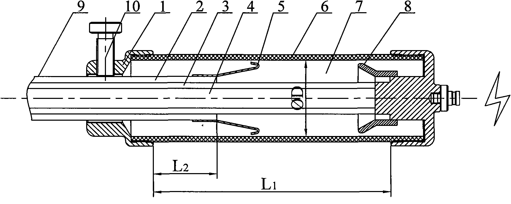
[0012] According to attached figure 1 The insulation shielding at both ends of the cable 9 is stripped to a certain length, and a metal stress cone 5 is set on the cable insulation shielding 2 at both ends of the cable 9, and then inserted into a plexiglass casing 6 equipped with a fluorocarbon compound 7 . The insulating medium adopts non-combustible fluorocarbons, which have very good insulating properties. The boiling point is 50-60 ° C. It is safe, reliable, cost-effective, and environmentally friendly. As long as the cable insulation and metal stress cones are completely immersed in the liquid, the localization of the cable can be carried out. Discharge, power frequency withstand voltage test.

Embodiment 2

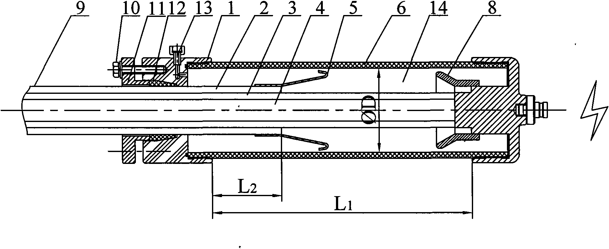
[0014] Sulfur hexafluoride 14 is used as the insulating medium, and a tapered sealing ring 12, a cover plate 11 and a hexagon head bolt 10 are added outside the metal cover 1 at the left end of the plexiglass sleeve 6, and the tapered sealing ring strengthens the gap between the metal cover and the outer diameter of the cable Sealing solves the short-term sealing problem at the left end, and the partial discharge and power frequency withstand voltage test of the cable can be carried out.

[0015] The present invention replaces the rubber prefabricated stress cone with the metal stress cone 5, the inner diameter of the metal stress cone is larger than the outer diameter of the cable insulation shield, and is fixed on the cable insulation shield 2, the cable insulation shield can be processed by the installation process of the Freon test terminal, and the installation convenience can be improved. continue.

[0016] According to the withstand voltage level and partial discharge r...


PUM

PropertyMeasurementUnit
Lengthaaaaaaaaaa
Lengthaaaaaaaaaa

Abstract

The invention relates to a power frequency withstand voltage and partial discharge test terminal structure of a medium-low voltage crosslinked cable. The test terminal structure comprises cable insulation after the insulating shield of the two ends of a cable terminal is stripped by a certain length, an insulating sleeve and insulating medium. The terminal structure is characterized by also comprising metal stress cones which are sleeved at fractures of insulating shielding layers of the cable; the end parts of the cable are axially abutted with high-voltage applying ends; the insulating sleeve is arranged outside the metal stress cones and the high-voltage applying ends; two ends of the insulating sleeve are provided with metal covers covering the two ends of the insulating sleeve; gaps among the cable insulation, the metal stress cones and the high-voltage applying ends in an insulating sleeve cavity are filled with insulating mediums which is one of fluorocarbon, sulfur hexafluoride, nitrogen or a mixed gas containing sulfur hexafluoride and nitrogen. The test terminal structure is fast and simple, replaces a Freon terminal and a rubber prefabricated stress cones, and simultaneously improves the installation performance and the partial discharge of the test terminal.

Description

technical field [0001] The invention relates to a terminal structure for partial discharge and power frequency withstand voltage tests of medium and low voltage cross-linked cables, and is suitable for how to carry out partial discharge and withstand voltage tests for 10kV and 35kV cross-linked cables. Background technique [0002] According to the requirements of relevant national standards, medium and low voltage cables should be subjected to partial discharge and power frequency withstand voltage tests, at 1.73U 0 Under the measurement of partial discharge, and to carry out 3.5U 0 5 minutes power frequency withstand voltage test. At present, the standards of some domestic cable manufacturers are higher than the national standards, that is, at 3.5U 0 The power frequency withstand voltage test and partial discharge test are carried out at the same time under the voltage, which puts forward higher requirements for the design of the test terminal. There are usually two m...

Claims


Application Information

Patent Timeline
IPC IPC(8): G01R1/02G01R31/12G01R31/08
Inventor 张荣徐操瞿金山冯岗杨文妃邵斌王福生
Owner 江苏亨通叁原电工科技有限公司
Learn More