Capacitor external expander

A technology for expanders and capacitors, applied in capacitors, electrical components, etc., to achieve the effects of good vacuum performance, convenient operation, and reduced labor intensity

Inactive Publication Date: 2015-12-16
DANDONG XINTAI ELECTRIC
View PDF4 Cites 0 Cited by
  • Summary
  • Abstract
  • Description
  • Claims
  • Application Information

AI Technical Summary

Problems solved by technology

[0003] Aiming at the oil compensation defects existing in the existing capacitors, the present invention proposes an external expander for capacitors that does not require oil pressure, is convenient to operate, and has a simple structure

Method used


Image

  • Capacitor external expander
  • Capacitor external expander
  • Capacitor external expander

Examples


Embodiment Construction

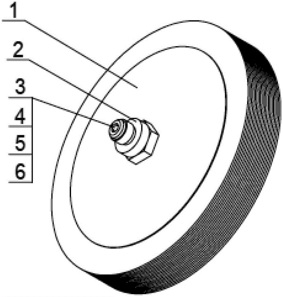
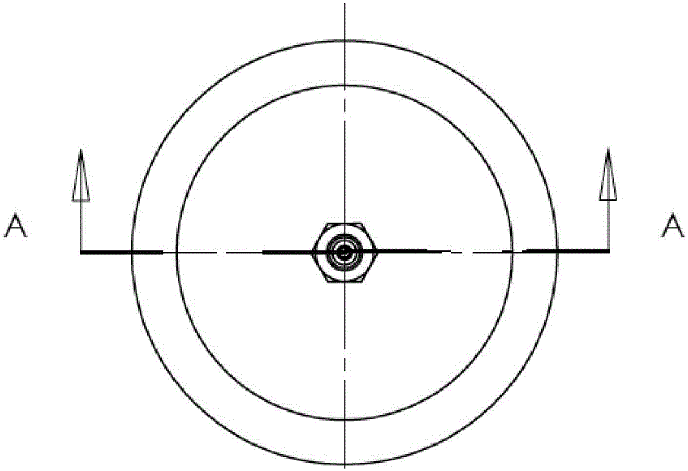
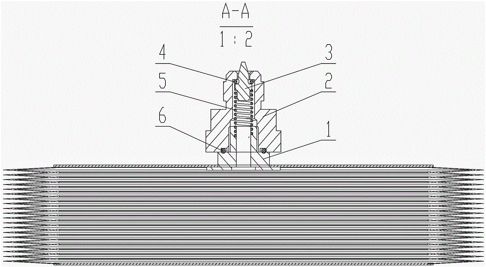
[0011] A capacitor external expander, such as figure 1 , figure 2 and image 3 As shown, it consists of expander body 1, connecting nut 2, oil drain valve 3, oil drain valve sealing ring 4, oil drain valve connecting spring 5 and expander sealing ring 6, wherein the expander body 1 and connecting nut 2 connection, an oil discharge valve 3 is provided on the expander body 1, an oil discharge valve connection spring 5 is provided on the oil discharge valve 3, and an oil discharge valve sealing ring 4 is provided between the connection nut 2 and the oil discharge valve 3 , An expander sealing ring 6 is provided between the expander body 1 and the connecting nut 2 . The compensation method and structure of the external expander are quite different from conventional expanders. The external expander adopts an internal oil-filled type, and the expander body is filled with oil in a vacuum state, and is tightly and sealed with connecting nuts and other components. Finally, it beco...


PUM


Abstract

Provided is a capacitor external expander, oiling by employing an inner oil type and under a vacuum state. The expander is in fixed connection with a connection nut, a sealing ring, a fuel drain valve, a spring, etc. to become an independent self sealing expander, and is then assembled with a capacitor body which goes through heating and vacuum-pumping processing and oils under high vacuum; the fuel drain valve of the expander is open, allowing a smooth oil path between the expander and the body. When the capacitor operates under a lower limit temperature, the volume of insulating oil in the body contracts, and the insulating oil in the expander performs compensation at any moment; and when the capacitor operates under an upper limit temperature, the volume of insulating oil in the body expands to jack the expanded insulating oil into the expander, guaranteeing that the insulating oil in the body can be effectively compensated when the capacitor is in a high and low temperature range. The capacitor external expander does not need to supply excess oil pressure, simplifies processes, and avoids waste caused by insulating oil overfall; meanwhile, the capacitor external expander has the characteristics of visual compensation effect and convenient operation, and can improve product quality, and obtain higher economic benefits and social benefits.

Description

technical field [0001] The invention relates to a power device used in a power grid, in particular to an external expander for a coupling capacitor and a capacitor voltage divider. Background technique [0002] Coupling capacitors and capacitive voltage dividers are electrical equipment used for power system carrier, communication and overvoltage protection. The voltage level of this capacitor is mostly 35kV to 750kV high-voltage products. In order to solve the main insulation, the outer casing is made of high-voltage electric porcelain bushing, the upper and lower flanges are two electrodes, and the capacitor core and insulating oil are installed inside. To compensate the expansion and contraction of insulating oil caused by the change of ambient temperature, the compensation method of building a conventional expander in the ceramic sleeve is currently used, and a certain amount of excess oil pressure must be applied to the capacitor to make it within the design temperature...

Claims


Application Information

Patent Timeline
Patent Type & Authority Applications(China)
IPC IPC(8): H01G2/00H01G2/10
Inventor 于莉影郭红云咸华
Owner DANDONG XINTAI ELECTRIC
Why Eureka
Try Eureka