Cinder soaking water concentrating and separating tank

A technology for separating ponds and grey water, applied in the sedimentation tank and other directions, can solve the problems of difficulty, reduced concentration effect, large power consumption, etc., to achieve the effect of reducing energy consumption and operating costs, and being conducive to ash discharge

Active Publication Date: 2009-12-30
GANSU GOLDEN BRIDGE GRP CO LTD
View PDF0 Cites 6 Cited by
  • Summary
  • Abstract
  • Description
  • Claims
  • Application Information

AI Technical Summary

Problems solved by technology

[0005] (1) Ash flushing consumes a lot of water;
[0006] (2) The amount of water discharged into the ash yard is large, resulting in external drainage;
[0007] (3) Long-distance transportation of large-flow mortar, high energy consumption,
[0008] (4) The thick slurry pipeline and the return water pipeline of the ash yard are relatively long, and the cost of scale prevention is high and difficult, which is not conducive to water reuse
The system still has the following deficiencies: (1) it occupies a large area; (2) it must have concentrating equipment, so the management and maintenance of mechanical equipment is complicated and the power consumption is large; (3) the pool body is low, which makes the concentrating effect somewhat (4) It is impossible to collect low-density hollow spherical ash particles in gray water, commonly known as "floating beads", which are a new type of building material

Method used


Image

  • Cinder soaking water concentrating and separating tank
  • Cinder soaking water concentrating and separating tank
  • Cinder soaking water concentrating and separating tank

Examples


Embodiment 1

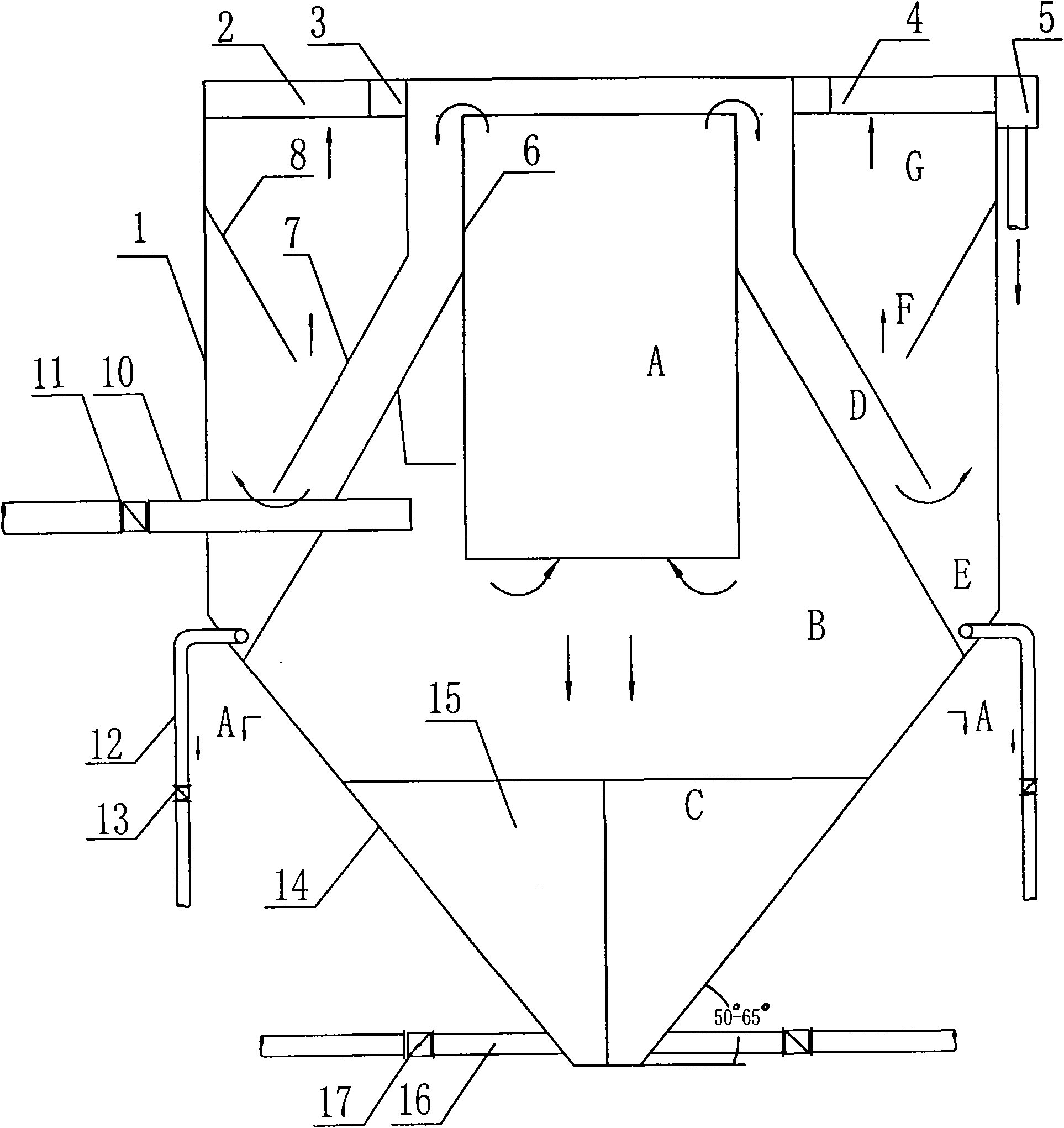
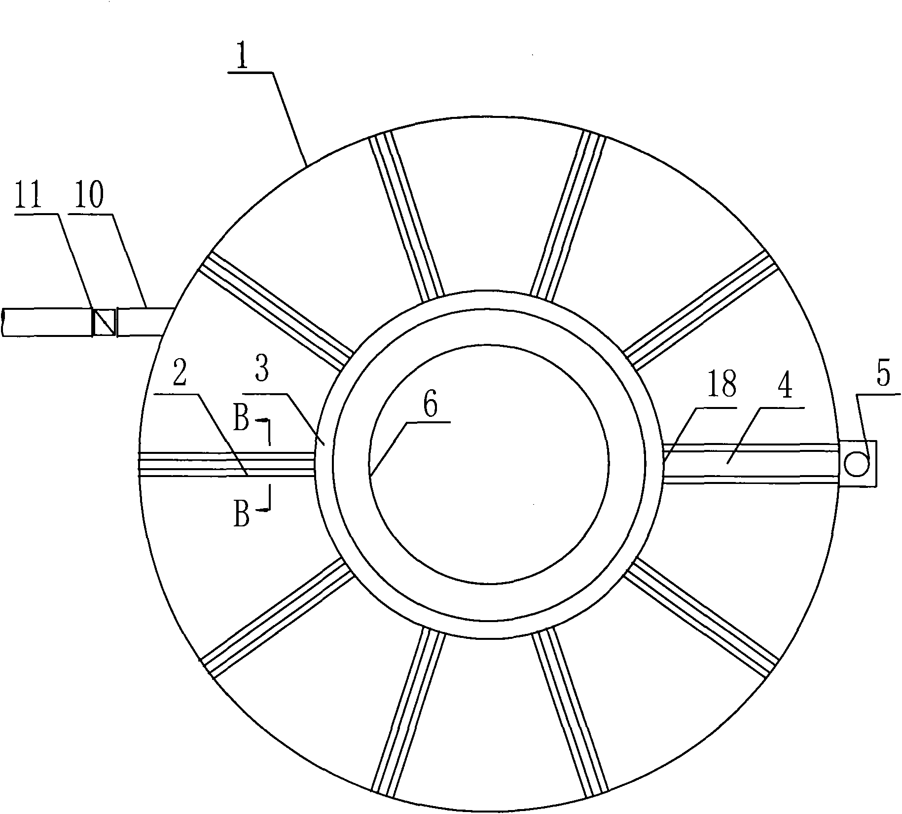
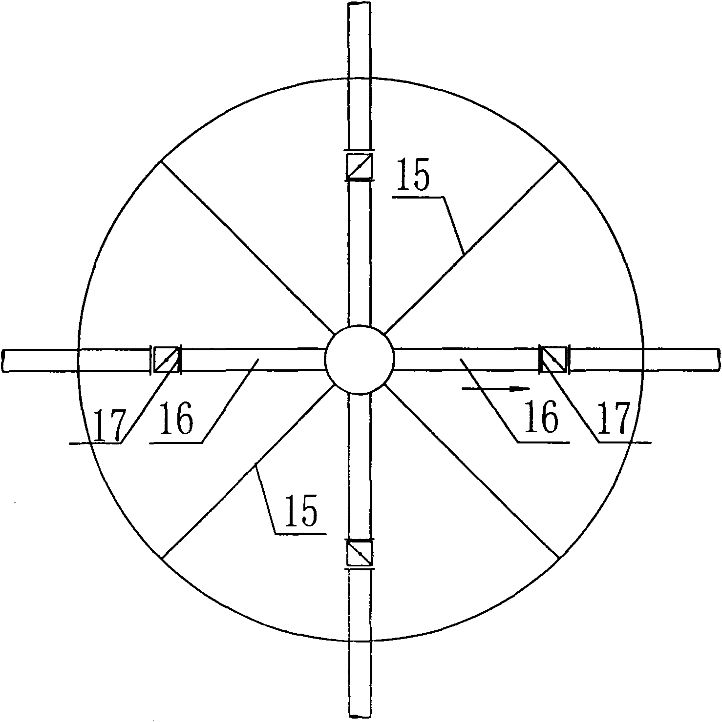
[0035] Example 1: see figure 1 , a gray water concentration and separation tank, comprising a concentration and separation tank body 1, a water collection tank is arranged above the concentration and separation tank body 1, and a concentration and separation tank separation type conical ash hopper is provided below the concentration and separation pool body 1 14, which is provided with a gray board 15; the middle part of the concentration and separation tank body 1 is provided with a straight reaction cylinder 6, the ash inlet pipe 10, and the valve 11 located at the ash inlet pipe 10 is arranged on the straight reaction cylinder 6, and the straight reaction cylinder 6 The upper part of the reaction cylinder 6 is the reaction zone A, the middle part is the cyclone precipitation zone B, and the lower part is the first concentration zone C; 1. Concentration and separation pool separated conical ash hopper 14 and conical reaction cylinder 9 form the second concentration zone E, w...


PUM

PropertyMeasurementUnit
Angleaaaaaaaaaa

Abstract

The invention relates to a concentration and separation processing facility for flushing cinder soaking water from a fuel electric plant, in particular to a cinder soaking water concentrating and separating tank which is mainly characterized in that a separated tapered cinder hopper (14) of the concentration and separation tank is arranged below a concentration and separation tank body (1) and is internally provided with a cinder separating plate (15); the middle part of the concentration and separation tank body (1) is provided with a straight reaction cylinder (6) which is a reaction region A on the upper part, a rotational flow settling region B in the middle and a first concentration region C at the lower part; the outer wall of the straight reaction cylinder (6) is fixedly connected with a tapered reaction cylinder (9); the concentration and separation tank body (1), the separated tapered cinder hopper (14) of the concentration and separation tank and the tapered reaction cylinder (9) forms a second concentration region E which is connected with a second cinder discharging pipe (12) and a valve (13) arranged on the second cinder discharging pipe (12); a flow guiding cylinder (7) is arranged outside the straight reaction cylinder (6) and forms a flow guiding region D together with the straight reaction cylinder (6) and the tapered reaction cylinder (9); a tapered cinder baffle (8) is arranged on the concentration and separation tank body (1), and a separation region F is formed between the tapered cinder baffle (8) and the flow guiding cylinder (7).

Description

technical field [0001] The invention relates to a treatment facility for concentration and separation of ash flushing and slag water for a thermal power plant, and a treatment method using the concentration and separation treatment facility for ash flushing and slag wastewater of the invention. Background technique [0002] At present, some thermal power plants in my country still use low-concentration direct-discharge ash flushing systems, and large-flow, low-concentration mortars are directly discharged into ash yards. Due to the large amount of water discharged into the ash yard, which exceeds the evaporation and leakage of the ash yard, drainage outside the ash yard occurs. Water bodies discharged directly to the outside often pollute the environment. [0003] In order to save water and reduce external drainage, many thermal power plants send the overflow water from the ash field back to the power plant for recycling ash, realizing the recycling of ash water. However, ...

Claims


Application Information

Patent Timeline
IPC IPC(8): B01D21/02
Inventor 王刚魏翠霞王爱莲胡建明
Owner GANSU GOLDEN BRIDGE GRP CO LTD
Why Eureka
Try Eureka