Strain test device for tension-torsion multi-shaft fatigue test under corrosion environment
A corrosive environment and strain testing technology, applied in measuring devices, instruments, scientific instruments, etc., can solve problems such as low cost and use of strain testing devices, and achieve the effects of avoiding corrosion, long service life, simple and lightweight structure
- Summary
- Abstract
- Description
- Claims
- Application Information
AI Technical Summary
Problems solved by technology
Method used
Image
Examples
preparation example Construction
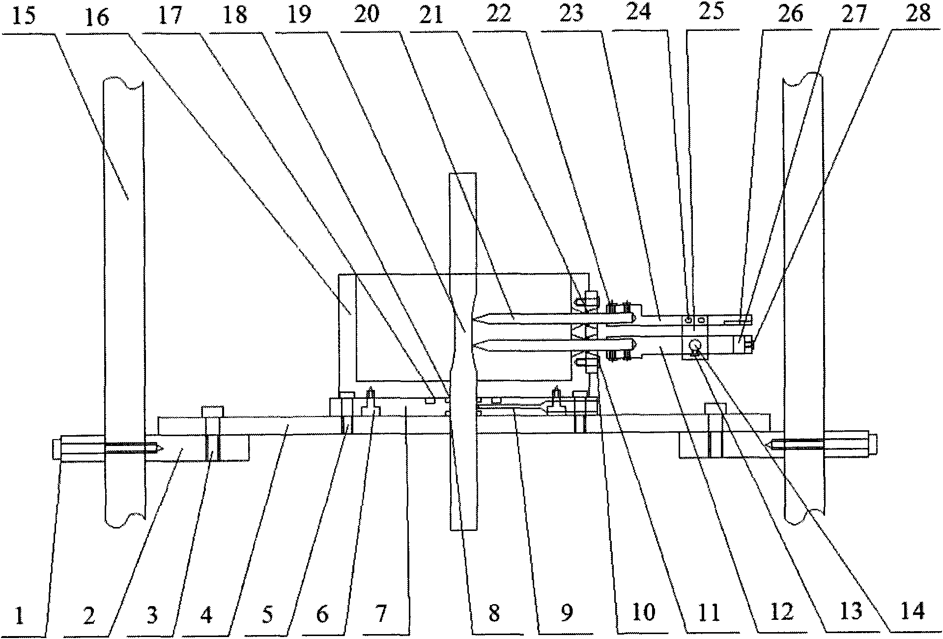
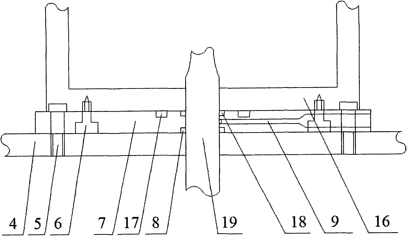
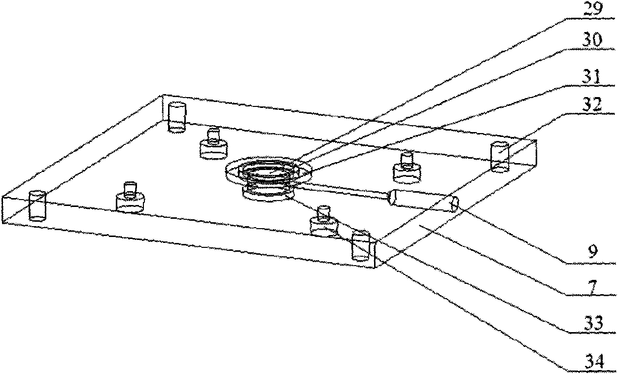
[0029] Preparation of the present invention: the lower support plate 2, the upper support plate 4, and the sealing baffle 10 are made of 304 austenitic stainless steel. The sealing rings 8, 17, 18, and 21 adopted in the system are all "O" type sealing rings. The electrolytic cell 16, the plexiglass plate 7, and the upper and lower induction brackets 12, 23 are made of plexiglass for the corrosion test. The torsional deformation sensing plate 25 and the stretching deformation sensing plate 26 are No. 45 steel. The bolts and screws used in the system are made of stainless steel. In order to prevent the corrosion of the ceramic thimble immersed in the corrosive solution and improve the service life of the strain test device, the thimble is made of non-metallic ceramic material. This kind of alumina ceramic material has the characteristics of stable chemical properties and high mechanical strength.
[0030] Installation of the present invention: the sample 19 is penetrated in th...
Embodiment 1
[0033] In this embodiment, the diameter of the tensile and torsion fatigue test sample is 10 mm, and the inner diameter of the electrolytic cell is 130 mm. Take the tension ring on the ceramic thimble as 60mm from the tip of the ceramic thimble. At this time, the distance between the tensile deformation sensor interface and the tension ring is 80mm, and the distance between the torsion deformation sensor interface and the tension ring The distance is 50mm.
[0034]Pass the ceramic thimble through the side wall of the electrolytic cell from the inside to the outside, install the side sealing ring and the sealing baffle in sequence, adjust the position of the ceramic thimble so that the distance between the top of the thimble and the side wall of the electrolytic cell is 60mm, and place the upper and lower induction brackets Fix it to the other side of the ceramic thimble, place a cuboid metal block with a thickness of 5mm between the upper and lower sensing brackets to ensure t...
Embodiment 2
[0037] In this embodiment, the diameter of the tensile and torsion fatigue test sample is 10 mm, and the inner diameter of the electrolytic cell is 154 mm. The tension ring on the ceramic thimble is taken as 72mm away from the tip of the ceramic thimble. At this time, the distance between the tensile deformation sensor interface and the tension ring is 68mm, and the distance between the torsional deformation sensor interface and the tension ring is The distance is 38mm.
[0038] Pass the ceramic thimble through the side wall of the electrolytic cell from the inside to the outside, install the side sealing ring and the sealing baffle in sequence, adjust the position of the ceramic thimble so that the distance between the top of the thimble and the side wall of the electrolytic cell is 60mm, and place the upper and lower induction brackets Fix it to the other side of the ceramic thimble, place a cuboid metal block with a thickness of 5mm between the upper and lower sensing brack...
PUM
| Property | Measurement | Unit |
|---|---|---|
| Thickness | aaaaa | aaaaa |
Abstract
Description
Claims
Application Information
 - R&D
- Intellectual Property
- Life Sciences
- Materials
- Tech Scout
- Unparalleled Data Quality
- Higher Quality Content
- 60% Fewer Hallucinations
Browse by: Latest US Patents, China's latest patents, Technical Efficacy Thesaurus, Application Domain, Technology Topic, Popular Technical Reports.
© 2025 PatSnap. All rights reserved.Legal|Privacy policy|Modern Slavery Act Transparency Statement|Sitemap|About US| Contact US: help@patsnap.com


