Projection bolt welding method, and welding apparatus

A welding device and welding method technology, applied in the direction of welding/welding/cutting items, auxiliary devices, welding equipment, etc., can solve the problems of difficulty in manufacturing, wear of movable parts, and installation space constraints, and achieve a quiet and compact factory environment. effect of size

Active Publication Date: 2010-01-06
青山好高
View PDF3 Cites 16 Cited by
  • Summary
  • Abstract
  • Description
  • Claims
  • Application Information

AI Technical Summary

Problems solved by technology

That is, the mounting position of the sensing part deviates, the stop position of the holding head deviates, and there is a problem that the movement of the holding head stops before the front end of the projection welding bolt is inserted into the receiving hole.
In addition, when moving the supply rod and the holding head, there is a problem that it is difficult to determine the stop position due to the action of inertia, which is not ideal for fine movements.
Or, when the movement amount of the holding head is reduced, the sensor parts must be arranged side by side in a narrow space, so the installation space is limited, and there is a problem that it is difficult to manufacture.
Furthermore, when the sensing part is mechanically movable, the movable part undergoes time-lapse changes such as wear and tear, so replacement of the sensing part and adjustment of the operating position are required, which is not ideal in terms of maintenance.
[0009] In addition, as a third point of concern, in the technologies disclosed in the above-mentioned patent documents, it is impossible to form a feeding control device that feeds out the projection welding bolts one by one in a reasonable manner, and to alleviate the impact of the projection welding bolts conveyed at high speed in the supply channel. The relationship between the stop unit and the forward and backward position of the supply rod

Method used


Image

  • Projection bolt welding method, and welding apparatus
  • Projection bolt welding method, and welding apparatus
  • Projection bolt welding method, and welding apparatus

Examples


Embodiment 1

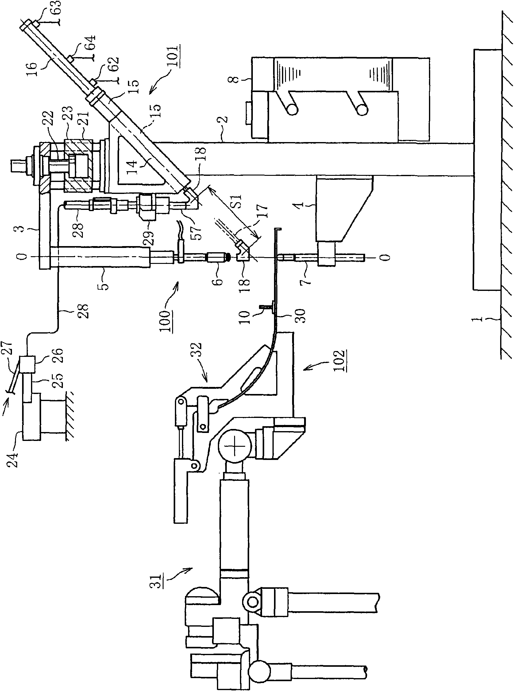
[0118] Figure 1~ Figure 7 Example 1 is shown.

[0119] Describes projection welding bolts.

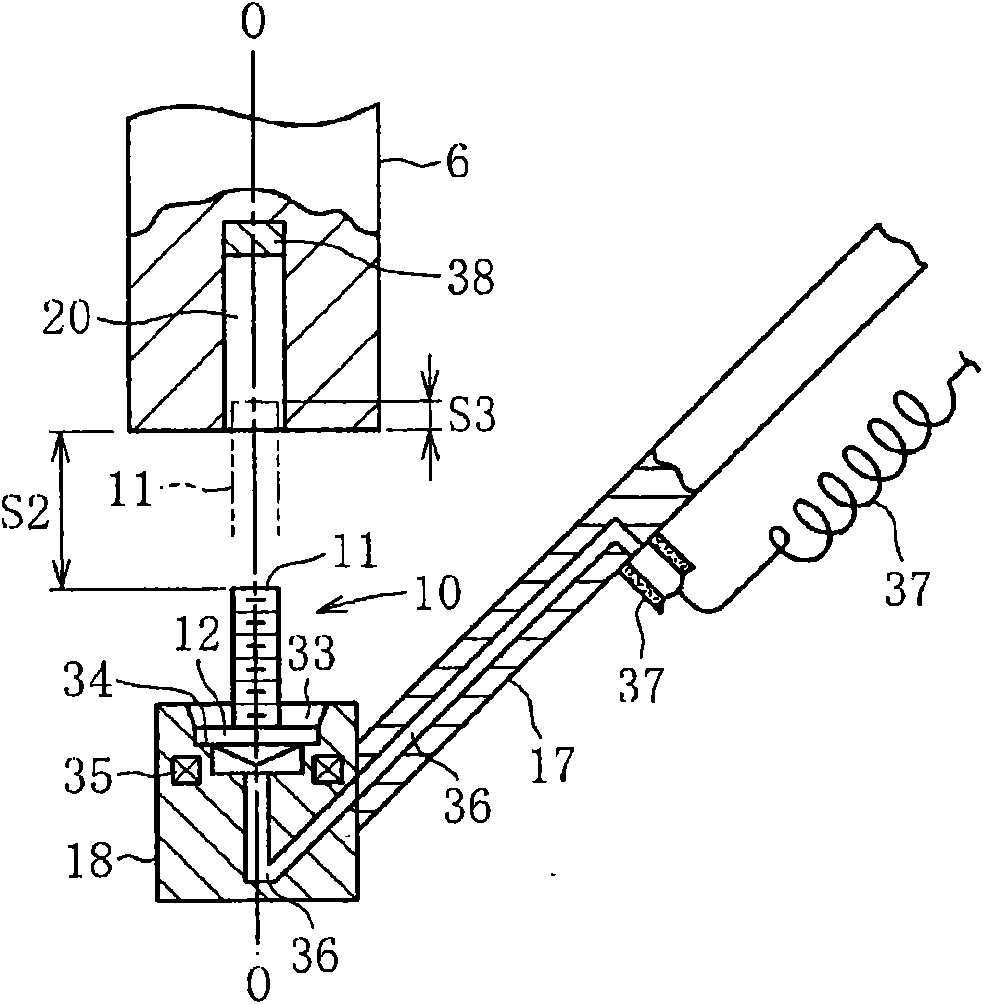
[0120] Such as Figure 2B As shown, the projection welding bolt 10 is made of iron, a circular flange portion 12 is integrally formed on the shaft portion 11 , and a circular welding protrusion 13 is provided on the flange surface opposite to the shaft portion 11 . Furthermore, the flange portion 12 is in a state concentric with the shaft portion 11 . The dimensions of each part are as follows, the diameter of the shaft portion 11 is 5 mm, the length of the shaft portion 11 is 23 mm, the diameter of the flange portion is 13 mm, the thickness of the flange portion is 1 mm, the diameter of the welding protrusion 13 is 9 mm, and the welding protrusion 13 The protrusion thickness is 1.2mm. In addition, in the following description, a projection welding bolt may be simply described as a bolt.

[0121] The overall welding device will be described.

[0122] Figure 1A It is a side view...

Embodiment 2

[0210] Figure 8 Example 2 is shown.

[0211] In this second embodiment, the resistance welding device 100 in the above-mentioned first embodiment is changed to a C-type welding torch. Accordingly, an engaging member 69 is fixed to the C-shaped arm 68 , and the piston rod 22 of the air cylinder 21 is fixed to the engaging member 69 . Furthermore, the above-mentioned base member 14 is connected to the cylinder 21 . In addition, another automatic device 70 is connected to the joint member 69 . Other configurations include unillustrated parts and are the same as those of the first embodiment, and the same symbols are assigned to components with the same functions. In addition, the operation and effect are also the same as those of the first embodiment described above.

Embodiment 3

[0213] Figure 9 Example 3 is shown.

[0214] In the previous embodiments, the supply rod 17 advances and retreats obliquely with respect to the electrode axis ○-○. In this third embodiment, the supply rod 17 advances and retreats in a direction perpendicular to the electrode axis ○-○. And after the supply rod 17 is raised by the air cylinder 21 and inserts the front end portion of the shaft portion 11 into the receiving hole 20, the insertion of the bolt 10 is completed by air jet. As a result, after the insertion is completed, the supply rod 17 is retracted without descending. That is, a rectangular movement indicated by symbol 71 is performed.

[0215] Therefore, in the third embodiment, after the bolt 10 is inserted into the receiving hole 20 by the air jet, the supply rod 17 is retracted from the original position by the air cylinder 16 . In the case of performing such an operation, the lowering operation of the supply rod 17 can be terminated in accordance with a retr...


PUM


Abstract

Provided are a welding method and a welding apparatus, which can start the proper advance of an electrode on the basis of both the positioning of the welded portion of a projection bolt with respect to a steel sheet and the completing state of the feed of the projection bolt with respect to the electrode. In the welding method, a bolt (10) held by a feed rod (17) is inserted into a receiving hole (20) of an electrode (6). Air is injected from a holding head (18) thereby to complete the bolt insertion into the receiving hole (20). Then, the feed rod (17) is retracted. After this, the electrode (6) is advanced to weld the bolt to a steel sheet (30) by the electric resistance method. In response to the signal issued by the insertion of the bolt and the signal issued by the positioning of the welded portion of the steel sheet (30), the electrode (6) is advanced relative to the steel sheet (30), and the pressurization and the power feed are then performed.

Description

technical field [0001] The present invention relates to a technique for welding projection welding bolts to steel plate parts by resistance welding. Background technique [0002] A technology is known from Patent No. 2509103. A projection bolt held on the holding head of the supply rod of the advancing and retreating type is inserted into the receiving hole provided in the resistance welding electrode, and then the electrode is passed through the electrode on standby. Projection welding bolts are welded on the steel plate parts. In addition, the technique disclosed in Japanese Patent Application Laid-Open No. 9-57458 synchronizes the moving operation of the steel plate member clamped by the robot and the operation of supplying the convex nut to the electrode. In addition, the technique disclosed in Japanese Patent Application Laid-Open No. 2003-236672 uses a signal obtained by the supply rod at a predetermined position in the middle of the reset stroke to move the electrode...

Claims


Application Information

Patent Timeline
Patent Type & Authority Applications(China)
IPC IPC(8): B23K11/14B23K103/04
CPCB23K9/206B23K11/0053B23K11/14B23K11/36B23K37/00B23P19/001B23P19/06B23K2103/04
Inventor 青山好高青山省司
Owner 青山好高
Why Eureka
Try Eureka