Method for measuring relay contact settling time and device thereof

A relay contact and stabilization time technology, applied in the electromagnetic field, can solve the problems of large error in measurement results, increased load voltage, complicated measurement process, etc., to achieve the effects of convenient operation, simple measurement steps, and high measurement accuracy

Active Publication Date: 2010-01-13
HARBIN INST OF TECH
View PDF0 Cites 22 Cited by
  • Summary
  • Abstract
  • Description
  • Claims
  • Application Information

AI Technical Summary

Problems solved by technology

[0003] At present, there are few special studies on the measurement of relay contact stabilization time. Relay manufacturers usually measure the contact voltage drop waveform manually with an oscilloscope to measure the stabilization time.
On the one hand, in order to improve the signal-to-noise ratio of the measured waveform, this method artificially increases the load voltage, which does not conform to the measurement conditions stipulated in the GJB standard.
On the other hand, the manual measurement method is greatly affected by subjective factors, the measurement results have large errors, the measurement process is complicated, and the efficiency is not high.

Method used


Image

  • Method for measuring relay contact settling time and device thereof

Examples


Embodiment 1

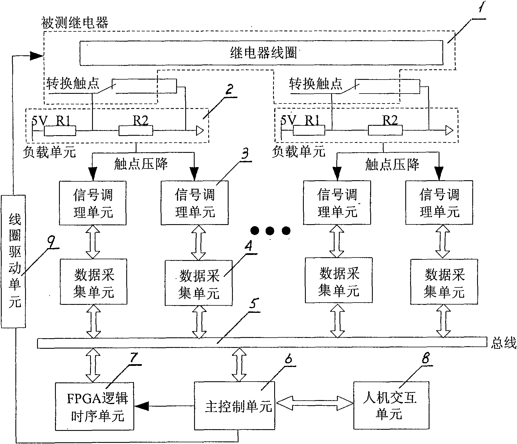
[0027] Example 1: Combining figure 1 , a kind of relay contact stable time measuring device of the present invention, it is by measured relay (1), load unit (2), signal conditioning unit (3), data acquisition unit (4), bus (5), main control unit (6), FPGA logic timing unit (7), human-computer interaction unit (8) and coil drive unit (9), it is characterized in that: the measured relay (1) is connected to the load unit (2), and the load unit ( 2) Connect the signal conditioning unit (3), the signal conditioning unit (3) is connected to the data acquisition unit (4), the data acquisition unit (4) is connected to the bus (5), and the bus (5) is connected to the main control unit (6) and the FPGA logic The timing unit (7), the main control unit (6) are respectively connected to the human-computer interaction unit (8), the FPGA logic timing unit (7) and the coil drive unit (9), and the coil drive unit (9) is connected to the relay under test (1) .

[0028]A relay contact stabiliz...

Embodiment 2

[0044] Example 2: Combining figure 1 , the relay contact stabilization time measuring device of the present invention comprises the following units:

[0045] The human-computer interaction unit realizes the parameter setting of the measuring device, the input of measurement instructions and the output of measurement results.

[0046] The main control unit receives the measurement instruction sent by the human-computer interaction unit, and sends the coil voltage control signal to the coil drive unit after analysis. The data sent by the data acquisition unit is processed by the main control unit, and the measurement results are obtained and transmitted to the human-machine interaction unit for display.

[0047] The coil drive unit receives the coil voltage control signal transmitted by the main control unit, amplifies the signal power and then isolates and outputs it to drive the relay coil.

[0048] Load unit, which provides load power supply and resistive load in compliance...


PUM


Abstract

The invention provides a method for measuring relay contact settling time and a device thereof, which can simultaneously measure six groups of changeover contacts and has a measurement resolution of 1mu s. The device comprises a relay under test, a load unit, a signal conditioning unit, a data acquisition unit, a bus, a main control unit, an FPGA logical time sequence unit, a human-computer interaction unit and a coil drive unit; wherein the relay under test is connected with the load unit; the load unit is connected with the signal conditioning unit which is connected with the data acquisition unit; the data acquisition unit is connected with the bus which is connected with the main control unit and the FPGA logical time sequence unit; the main control unit is respectively connected with the human-computer interaction unit, the FPGA logical time sequence unit and the coil drive unit; and the coil drive unit is connected with the relay under test. The invention has the advantages of high accuracy of measurement, automatic measurement process, simple measurement procedures, easy operation, small size and light weight of measuring devices, and the like.

Description

(1) Technical field [0001] The invention relates to electromagnetic technology, in particular to a method for measuring the stable time of a relay contact and a device thereof. (2) Background technology [0002] The relay contact stabilization time can effectively reflect the contact reliability of the relay contact, and is an important measurement parameter in the screening test before the product leaves the factory. GJB requires that the contact stabilization time must be measured for aerospace relays above level 5 before leaving the factory. Aerospace relay contact stabilization time is defined as the maximum time allowed for the contacts to reach and maintain a static contact resistance state after the relay action and release time. At present, there are standard regulations for the measurement method and measurement conditions of the contact stabilization time of aerospace relays. Taking GJB 65B-99 as an example, the standard stipulates that the measurement of the stab...

Claims


Application Information

Patent Timeline
Patent Type & Authority Applications(China)
IPC IPC(8): G01R31/327
Inventor 翟国富李孝臣余琼李冰任万滨王其亚叶雪荣
Owner HARBIN INST OF TECH
Why Eureka
Try Eureka