
Intelligent type adjustable solar battery device

A technology of solar cells and solar panels, applied in the field of solar cells, can solve problems such as economic loss, high cost, and inability to avoid wind, and achieve the effects of good market competitiveness, low manufacturing cost, and convenient installation

Inactive Publication Date: 2010-01-13
DONGMENG STAINLESS STEEL YUEQING CITY
View PDF0 Cites 21 Cited by
  • Summary
  • Abstract
  • Description
  • Claims
  • Application Information

AI Technical Summary

Problems solved by technology

[0006] In addition, this installation method, when the southern city encounters a typhoon in summer, it cannot take shelter from the wind, which may damage the solar cell device and cause economic losses
[0007] At present, someone has also designed a timely automatic tracking device for sunlight, but its structure is complex, the cost is high, and because of its bulky size, it is not suitable for installation in substations.

Method used


Image

  • Intelligent type adjustable solar battery device
  • Intelligent type adjustable solar battery device
  • Intelligent type adjustable solar battery device

Examples


Embodiment 1

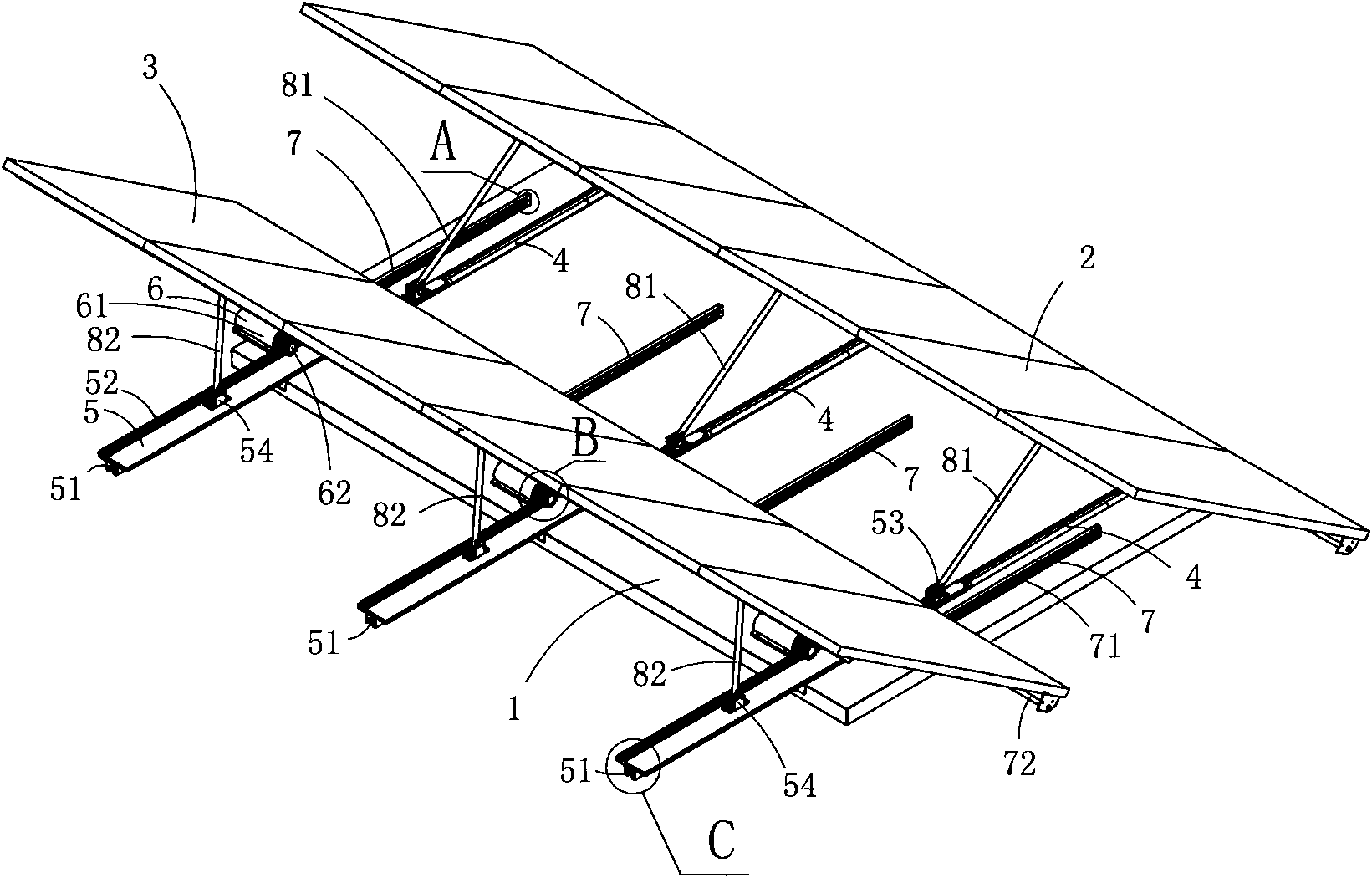
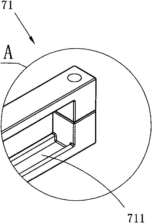
[0028] Figure 1 to Figure 8 A specific embodiment of the invention is shown in which, figure 1 It is a schematic diagram of a three-dimensional structure of the present invention; figure 2 yes figure 1 A schematic diagram of the structure of the shown intelligent adjustable solar cell device viewed from the side; image 3 yes figure 1 Partial enlarged schematic diagram of A; Figure 4 yes figure 1 Structural view of the longitudinal section of the limiting rail in the shown intelligent adjustable solar cell device; Figure 5 yes figure 1 Partial enlarged schematic diagram of B in middle; Figure 6 yes figure 1 Partial enlarged schematic diagram at C; Figure 7 yes figure 1 A schematic diagram of the structure of the cooperation between the moving guide rail and the static sliding rail in the intelligent adjustable solar cell device shown; Figure 8 yes figure 1 A schematic diagram of the structure of the smart adjustable solar cell device when two solar cell pane...

Embodiment 2

[0036] This embodiment is basically the same as Embodiment 1, except that each of the limiting rails 71 is a slide rail, and the rotating shaft 72 is provided with a slider at a position corresponding to each of the limiting rails 71 ; The slider matches the shape of the limiting rail 71 .

Embodiment 3

[0038] This embodiment is basically the same as Embodiment 1, the difference is that each moving guide rail 5 is also provided with a linkage device, and the linkage device is two angle steels fixed on the three moving guide rails 5, and the three angle steels are connected by the angle steel The moving guide rails are fixedly connected, so that only one electric drive device 6 is needed in this embodiment to drive the three moving guide rails 5 to slide on the static slide rails. The advantage of this embodiment is lower cost.

[0039] The advantage of above-mentioned embodiment 1 to embodiment 3 is:

[0040] (1) In the above-mentioned embodiments 1 to 3, the moving guide rail is driven by the driving gear to reciprocate along the installation direction of the static slide rail. During the reciprocating motion, it also synchronously drives the The first pin seat and the second pin seat on the top move, so that the first pin seat drives the first solar cell panel to rotate a ...


PUM


Abstract

The invention discloses an intelligent type adjustable solar battery device comprising a base, a first solar battery plate and a second solar battery plate, wherein the base is provided with a static sliding rail, dynamic guide rails, an electric driving device and a limiting device; the first solar battery plate is articulated with the base along a longitudinal direction; the limiting device comprises a limiting rail arranged along a transverse direction and a rotating shaft arranged along the longitudinal direction, wherein the rotating shaft can reciprocate along the transverse direction; the second solar battery plate is articulated with the rotating shaft; each dynamic guide rail is provided with a chute, a rail cog, a first pin seat and a second pin seat; both ends of a first connecting rod are respectively articulated with the first pin seat and a first articulation seat, and both ends of a second connecting rod are respectively articulated with the second pin seat and a second articulation seat; the electric driving device comprises a motor and a driving gear; the first solar battery plate is provided with the first articulation seat, and the second solar battery plate is provided with the second articulation seat. The invention can automatically adjust the solar battery plates to a proper angle according to the requirement of a system.

Description

technical field [0001] The invention belongs to the technical field of solar cells, and in particular relates to an adjustable solar cell device. Background technique [0002] At present, some substations have installed solar cell devices on their tops, and use the solar cell devices to obtain electricity to meet the electricity needs of some of their built-in electrical appliances, thereby reducing their own energy consumption costs. [0003] As we all know, how to make the solar cell module absorb sunlight to the maximum and output the maximum power depends on the installation angle of the solar cell module. Theoretically, only when the sunlight is vertically irradiated on the surface of the solar cell can there be maximum power output. [0004] At present, most of the brackets used to install solar cell modules are welded by angle steel. Once the welding is completed, the angle of the solar cell panel will be fixed and cannot be adjusted. [0005] The sun changes from n...

Claims


Application Information

Patent Timeline
Patent Type & Authority Applications(China)
IPC IPC(8): H01L31/042H02S20/30
CPCF24J2/5266F24J2/541F24J2/5239F24J2002/5486F24J2002/5462Y02E10/47F24S25/16F24S30/20F24S30/425F24S2030/134F24S2030/16Y02E10/50
Inventor 何建强
Owner DONGMENG STAINLESS STEEL YUEQING CITY
Learn More