Optical doubling frequency laser interference measurement system and optical doubling frequency laser interference measurement method for displacement of special geometric point

An optical frequency doubling and laser interference technology, which is applied in the field of optical metrology, can solve the problem that the measurement of special geometric points cannot be measured accurately.

Inactive Publication Date: 2010-01-20
NAT INST OF METROLOGY CHINA
View PDF5 Cites 18 Cited by
  • Summary
  • Abstract
  • Description
  • Claims
  • Application Information

AI Technical Summary

Problems solved by technology

[0002] Since the advent of the laser in 1958, coupled with the development of modern microelectronics technology, the laser interferometer has become one of the most accurate length and position measurement devices. With the discovery of the polarization characteristics of the laser, the polarization laser interferometer has been applied in high-resolution In force displacement measurement, it has the characteristics of high light application efficiency; the principle of a typical Michelson polarization laser interferometer is to divide a beam of circularly polarized laser light into P light and S light through a polarization beam splitter PBS, which are reflected by a reference mirror and a moving reflection Mirror and quarter-wave plate return to the original path, and meet again at the split point, and finally form interference, in which the moving mirror is often integrated with the measured object. When measuring, the measured object must move along the guide rail. The point to be measured is often where the moving mirror is located, and it cannot be accurately measured for special geometric points

Method used


Image

  • Optical doubling frequency laser interference measurement system and optical doubling frequency laser interference measurement method for displacement of special geometric point
  • Optical doubling frequency laser interference measurement system and optical doubling frequency laser interference measurement method for displacement of special geometric point
  • Optical doubling frequency laser interference measurement system and optical doubling frequency laser interference measurement method for displacement of special geometric point

Examples


Embodiment 1

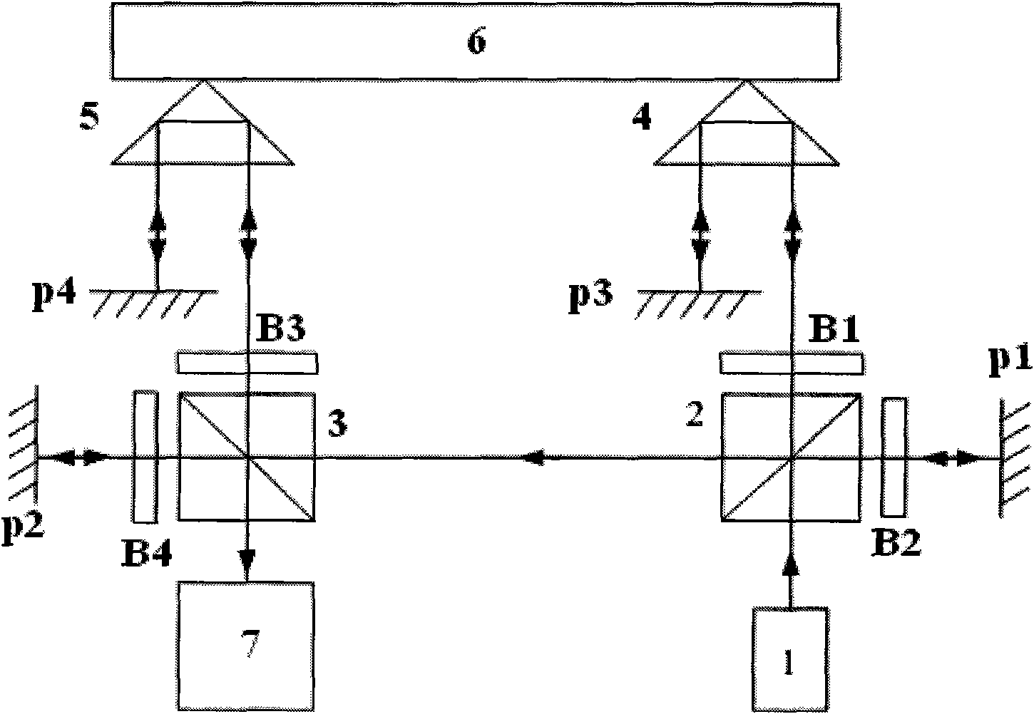
[0049] Such as figure 1 As shown, the first polarization beam splitter 2 is set on the output optical path of the laser 1, and the beam splitting surface of the polarization beam splitter is 45° to the output optical path of the laser. The first polarization beam splitter 2 divides the output light of the laser 1 into two beams of polarized light: Reflected light and transmitted light, wherein the reflected light re-enters the polarization beam splitter after passing through the λ / 4 wave plate B2 and the fixed mirror P1, at this time the polarization state changes, and is transmitted from the polarization beam splitter 2 to enter the second polarization Beam splitter 3, the beam-splitting surface of polarizing beam splitter 3 and polarizing beam splitter 2 are 90° to each other, the light transmitted from polarizing beam splitter 2 is also transmitted in polarizing beam splitter 3, and passes through λ / 4 wave plate B4 and fixed mirror P2 Afterwards, re-enter the polarization b...

Embodiment 2

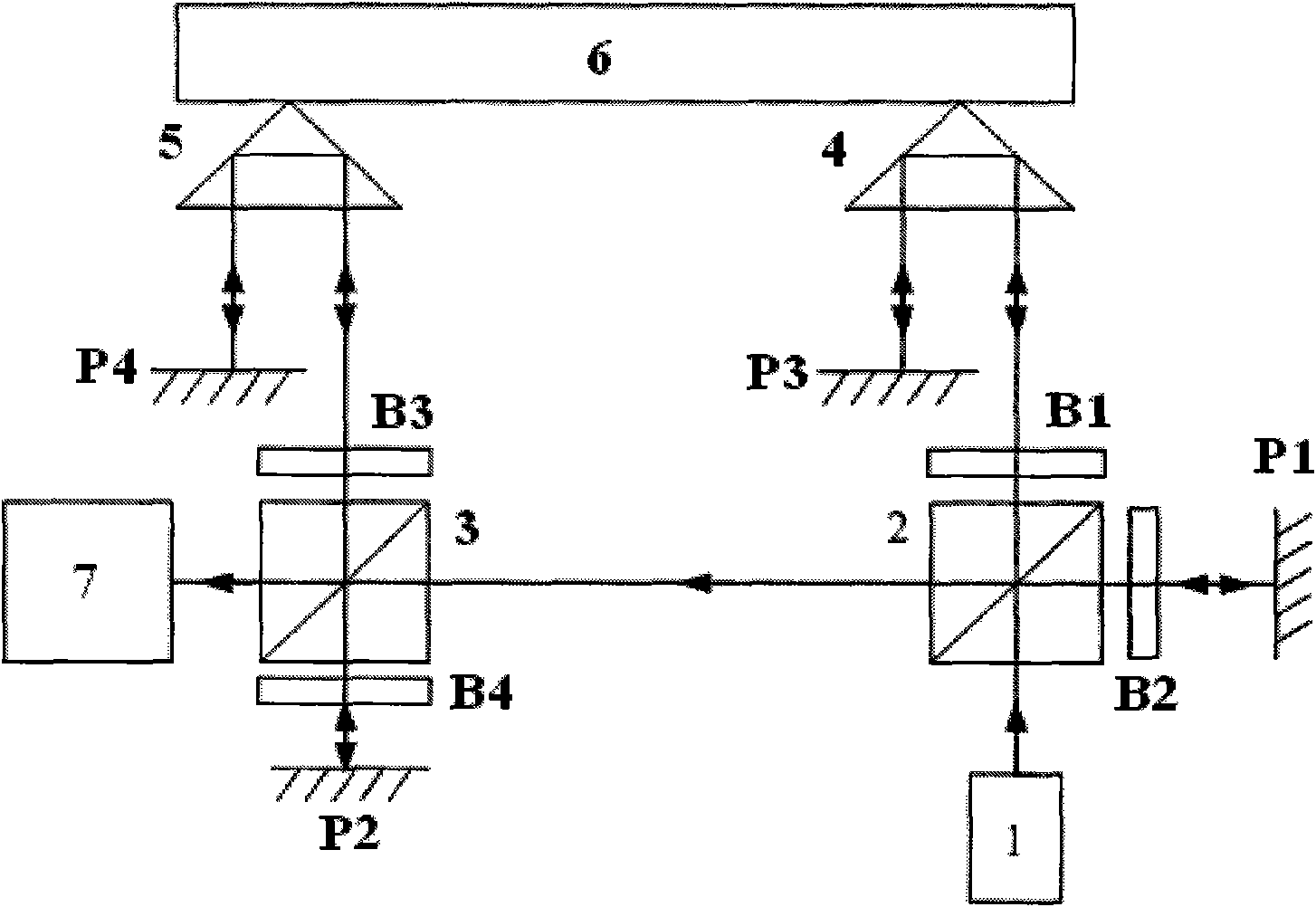
[0051] Such as figure 2 As shown, the difference from Example 1 is that the beam-splitting planes of the polarization beamsplitter 3 and the polarization beamsplitter 2 are parallel to each other, and the measurement light enters the polarization beamsplitter 3 and is reflected to the λ / 4 wave plate B4 and the fixed mirror P2, and then enters the polarization beamsplitter again. After the beam splitter 3 transmits, passes through the λ / 4 wave plate B3, the corner cube prism 5 and the plane mirror P4, and returns to the original optical path, and the reference light reflected and transmitted on the beam splitting surface of the polarization beam splitter 3 interferes in the coherent and receiving device 7 .

Embodiment 3

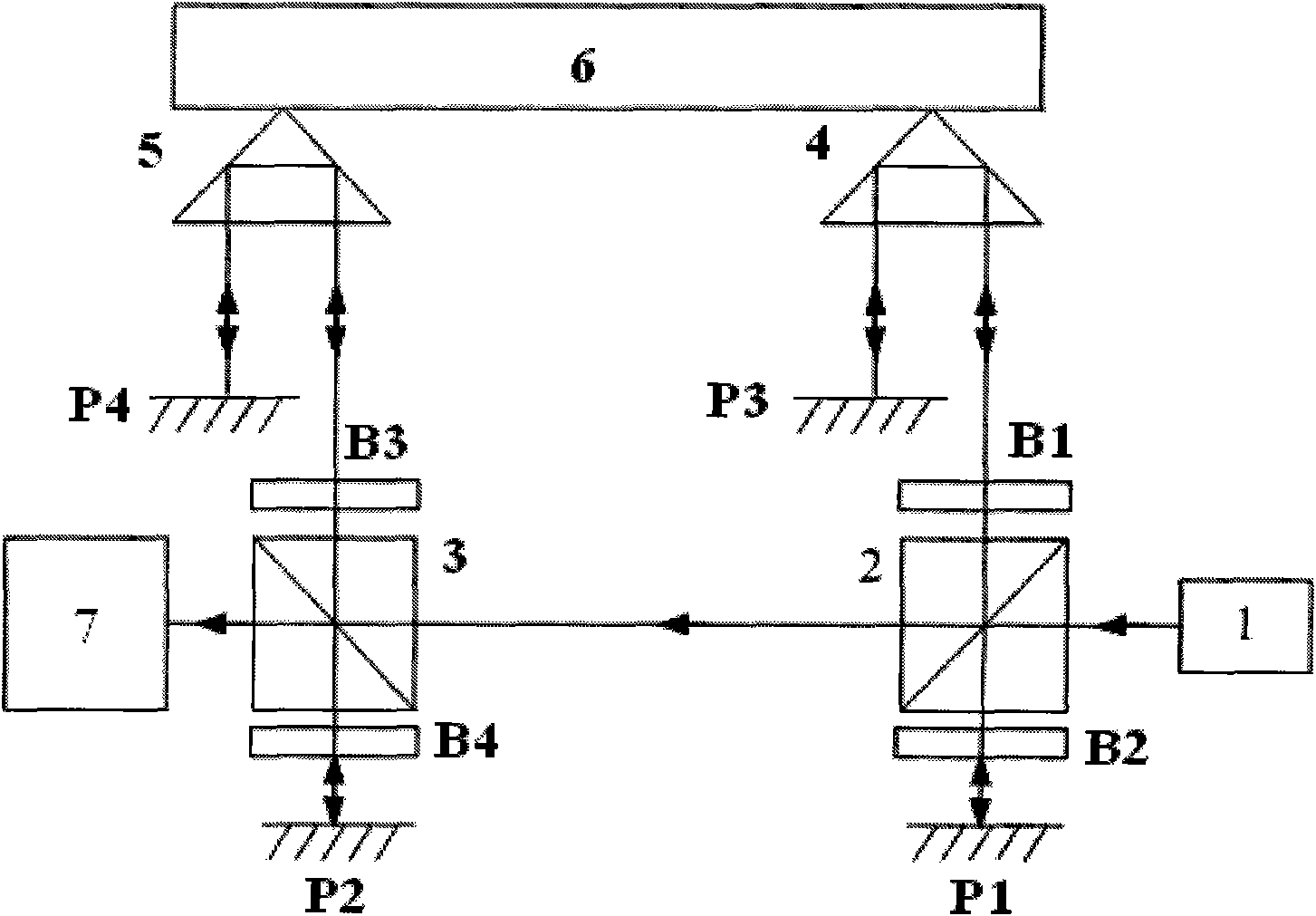
[0053] Such as image 3 As shown, the polarization beam splitter 2 splits the output light of the laser 1 into two beams of polarized light: reflected light and transmitted light. Among them, the transmitted light enters the coherent and receiving device 7 as a reference beam after passing through the polarization beam splitter 2 and 3; The mirror 2 transmits, enters the λ / 4 wave plate B1 and then enters the corner cube prism 4, is reflected by the plane mirror P3 and returns to the original optical path, and the polarization state of the beam changes again before re-entering the polarization beam splitter 2, and is reflected by the polarization beam splitter 2 splitting surface , enter the polarizing beam splitter 3, the beam splitting surface of the polarizing beam splitting mirror 3 and the polarizing beam splitting mirror 2 are 90° mutually, so that the light beam is reflected on the polarizing beam splitting mirror 3 beam splitting surface and enters the λ / 4 wave plate B3...


PUM


Abstract

The invention belongs to the field of optical measurement and relates to an optical doubling frequency laser interference measurement method for the displacement of a special geometric point. The method comprises the following steps: symmetrically placing two pyramid prisms on two sides of a special geometric point on a measured object; accurately obtaining the displacement of a central point by utilizing the displacement sum of two points; and dividing laser output light into measurement light and reference light by utilizing a polarization light splitter, wherein the measurement light respectively passes through the two pyramid prisms and returns twice in each pyramid prism and the measurement light moves for 8 Delta if a measured point moves for one Delta so that the optical octuple frequency of interference measurement is realized and the measurement accuracy is improved. Because the measurement light returns along the prior path in the pyramid prisms, even if the measured object moves in a plane vertical to a motion direction according to the characteristics of the pyramid prisms, the measurement accuracy of the motion direction is not influenced so that the method can be more widely applied. The invention can be applied to the measurement of non-guide rail movement and other complicated movements with more measured object freedom.

Description

technical field [0001] The invention belongs to the field of optical metrology, and relates to an optical frequency-doubled laser interferometry method for displacement of a special geometric point, which is suitable for a special geometric point where the measured point is a measured object. For example, the measured object is hollow and the measurement point is blocked. or sensitive areas. Background technique [0002] Since the advent of the laser in 1958, coupled with the development of modern microelectronics technology, the laser interferometer has become one of the most accurate length and position measurement devices. With the discovery of the polarization characteristics of the laser, the polarization laser interferometer has been applied in high-resolution In force displacement measurement, it has the characteristics of high light application efficiency; the principle of a typical Michelson polarization laser interferometer is to divide a beam of circularly polariz...

Claims


Application Information

Patent Timeline
Patent Type & Authority Applications(China)
IPC IPC(8): G01B11/02G02F1/35
Inventor 鲁云峰张钟华贺青陈允昌李正坤赵建亭韩冰李辰
Owner NAT INST OF METROLOGY CHINA
Why Eureka
Try Eureka