
Compressor for a turbocharger and method for cooling thereof

A technology for compressors and compressor impellers, which is applied to parts of pumping devices for elastic fluids, gas turbine devices, machines/engines, etc., and can solve the problems of reducing the life of turbochargers, centrifugal force of small rotating masses, and deterioration efficiency, etc. problem, achieve the effect of reducing the rotating mass, reducing the size and prolonging the life

Inactive Publication Date: 2010-01-20
MAN B & W DIESEL AS
View PDF4 Cites 5 Cited by
  • Summary
  • Abstract
  • Description
  • Claims
  • Application Information

AI Technical Summary

Problems solved by technology

[0004] This high temperature shows the enormous thermal stress of the compressor, especially on the compressor wheel, which is preferably made of light metal, such as aluminum alloy, in order to keep the rotating mass small and the resulting centrifugal force, which can cause loose Opening effect (Entfestigung) and thus reducing the service life of the turbocharger
At the same time, the temperature rise of the working medium reduces the (gas) filling of the combustion chambers of the internal combustion engine and deteriorates the efficiency

Method used


Image

  • Compressor for a turbocharger and method for cooling thereof
  • Compressor for a turbocharger and method for cooling thereof
  • Compressor for a turbocharger and method for cooling thereof

Examples


Embodiment Construction

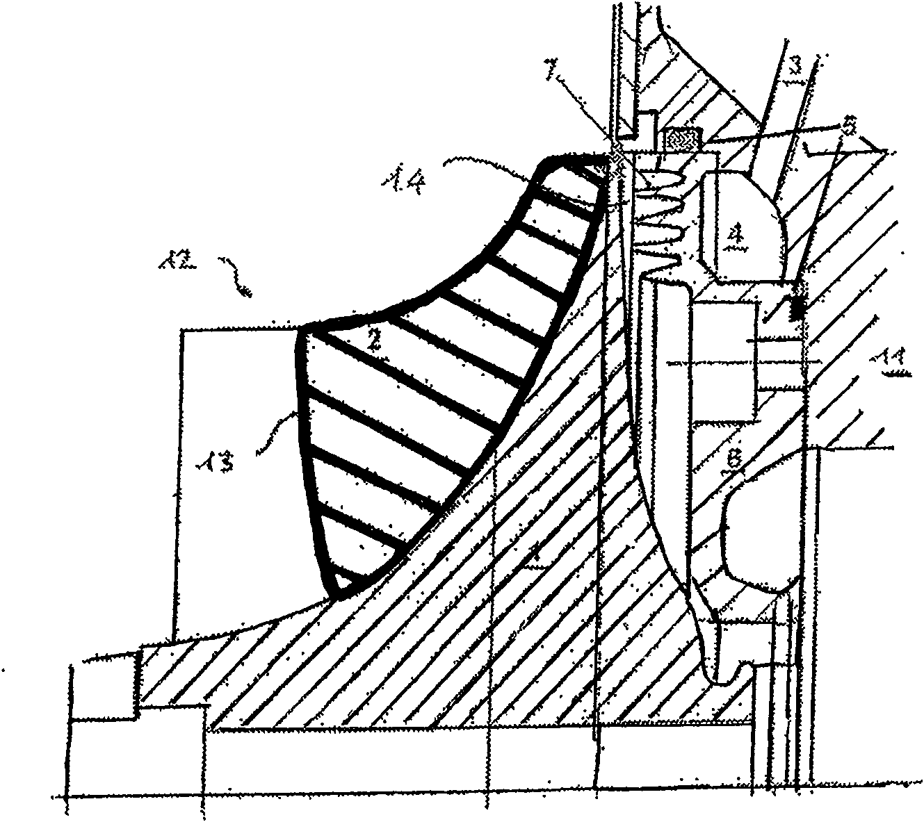
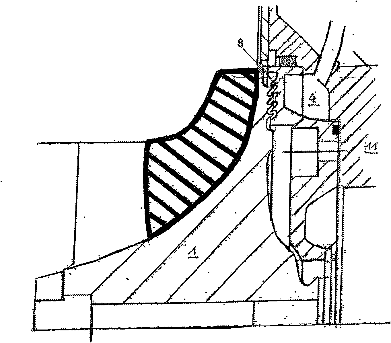
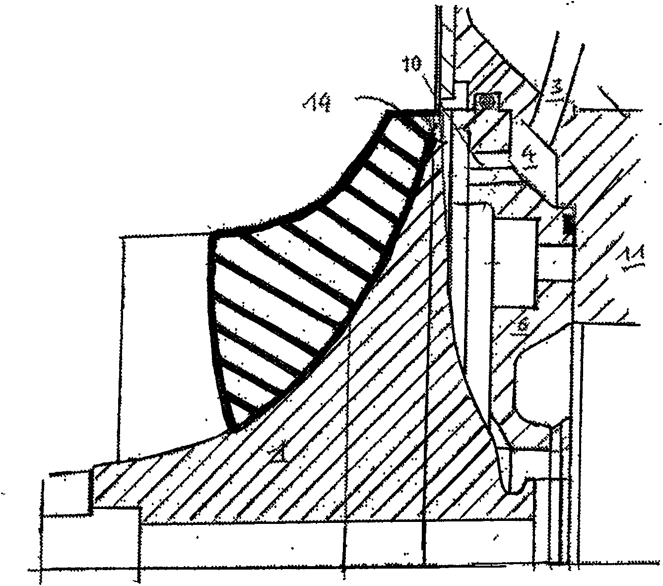
[0033] figure 1 A side view of components of a compressor according to a first embodiment of the present invention is schematically illustrated. The compressor comprises a compressor wheel 1 , which is mounted rotatably in a compressor housing 11 and is separated from the compressor housing by a radial gap 14 . A plurality of compressor blades 12 curved in the circumferential direction are distributed on the hub circumference of the compressor impeller, figure 1 Only one is shown.

[0034] The compressor blade 12 is made of aluminum oxide AI 2 o 3 A heat input-reducing coating 2 is produced, which in the exemplary embodiment extends from the inlet edge 13 of the sub-blade set to the impeller outlet and is applied by thermal spraying. Although in figure 1 It cannot be recognized that the surface area of ​​the compressor hub is also provided with a coating in this area.

[0035] The air is accelerated by the compressor blades 12 in radial and circumferential directions, de...


PUM


Abstract

A compressor, particularly a radial compressor, for a turbocharger comprises a compressor impeller (1), which is rotatably received in a compressor housing, wherein cooling fluid flows through a part (6) of the compressor housing adjacent to the compressor impeller. The compressor impeller comprises at least partially a heat input reducing coating (2).

Description

【Technical field】 [0001] The invention relates to a compressor for a turbocharger and a cooling method thereof according to the preamble of claim 1 . 【technical background】 [0002] In a turbocharger, the working medium, especially air, is compressed by a compressor for combustion in the internal combustion engine. This compressor is connected to a turbine, which is driven by the exhaust gas of the internal combustion engine. [0003] Through the frictional heat generated between the moving compressor wheel and the compressor housing or the working medium accommodating the compressor wheel, but first by the compression of the working medium itself, high temperatures are generated at the compressor wheel outlet, especially at the compressor wheel outlet. It is thus possible, for example, to heat from room temperature to over 200° C. at a compression ratio of four gases. [0004] This high temperature shows the enormous thermal stress of the compressor, especially on the com...

Claims


Application Information

Patent Timeline
IPC IPC(8): F02C6/12F04D29/58
CPCF01D5/046F01D25/14F04D29/023F04D29/584F05D2220/40F05B2220/40F01D5/288F05C2203/08F05D2300/21F05D2260/232F05B2260/232F04D29/083F04D29/284F05D2300/2112F05D2300/2118F01D5/28F02C6/12F04D29/58
Inventor M·迈耶F·沃德克H·莫格尔
Owner MAN B & W DIESEL AS
Learn More