Up-flow reactor and application thereof

A reactor, up-flow technology, used in chemical instruments and methods, petroleum industry, chemical/physical processes, etc., can solve the problem of limited gas distribution effect, high requirements for distributor level, and reduced reactor space utilization, etc. problem, to achieve the effect of overcoming bubble drift

Active Publication Date: 2012-05-30
CHINA PETROLEUM & CHEM CORP +1
View PDF6 Cites 3 Cited by
  • Summary
  • Abstract
  • Description
  • Claims
  • Application Information

AI Technical Summary

Problems solved by technology

Therefore, the disadvantage of this design is similar to that of US4639354. A stagnant air chamber will be generated under the perforated plate, which reduces the utilization rate of the reactor space, and the small pore structure is easily blocked by impurities.
At the same time, due to the design of side openings, the sparger has high requirements on the level of processing and installation. Once the initial distribution is not ideal, the effect of the middle sparger on improving gas distribution is limited.

Method used


Image

  • Up-flow reactor and application thereof
  • Up-flow reactor and application thereof
  • Up-flow reactor and application thereof

Examples


Embodiment Construction

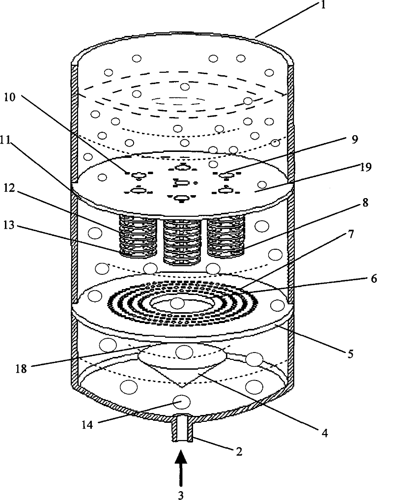
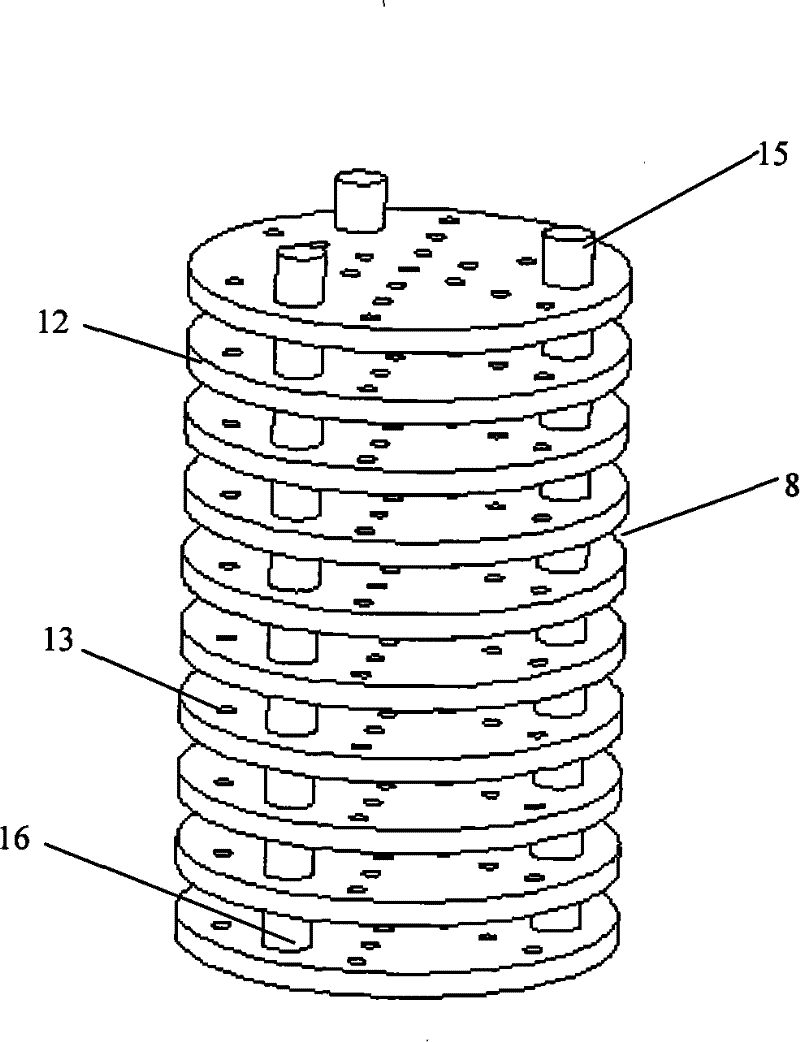
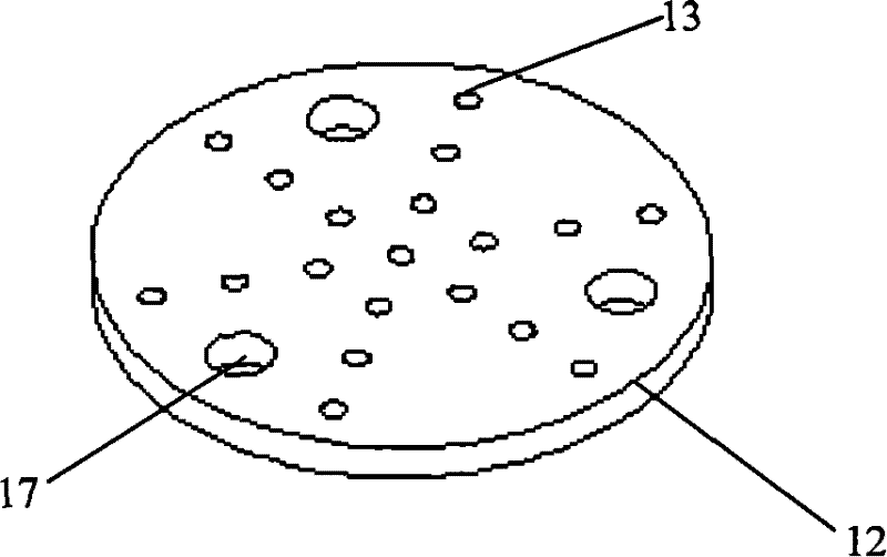
[0036] first combined with Figure 1~3 The intermediate distributor 19 will be described. Such as figure 2 and image 3 As shown, the sieve plate string structure 8 is composed of 10 small sieve plates 12, the small sieve plates 12 have hole structures 13, and the hole structures 13 are distributed in concentric circles here; there are bolt positioning holes 17 on the side of the small sieve plates 12 , use the positioning bolt 15 to pass through the hole 17, and then put on the distance tube 16 whose inner diameter is larger than the diameter of the hole 17, and then pass through another small sieve plate and another distance tube in turn, and the plate string can be made after multiple operations Structure 8; then pass the positioning bolts 15 through the bolt positioning holes 10 on the perforated sieve plate 11 and fix them to complete the manufacture of the intermediate distributor 19.

[0037] The following is attached by figure 1 The present invention will be descr...


PUM

PropertyMeasurementUnit
diameteraaaaaaaaaa
diameteraaaaaaaaaa
diameteraaaaaaaaaa

Abstract

The invention discloses an up-flow reactor, which comprises an initial distributor positioned at the bottom of the reactor and an intermediate distributor above the initial distributor. The initial distributor consists of a conical traverse baffle and a sieve plate positioned above the conical traverse baffle; and the intermediate distributor consists of an open pore sieve plate and a sieve platestring structure. The up-flow reactor provided by the invention can realize even distribution of gas in the reactor in short distance so as to improve the utilization rate of a catalyst and increase the space of a catalyst bed layer in the reactor. The up-flow reactor of the invention is particularly applied to a hydrogenation process of heavy oil (comprising wax oil, residual oil, coal liquefiedoil and the like).

Description

technical field [0001] The invention relates to an upflow reactor and its application. Background technique [0002] Both the trickle bed and the packed bubbling bed are three-phase reactors filled with catalyst, and the difference between them lies in the different operation modes. In a trickle bed, the liquid and gas reactants flow through the catalyst bed from top to bottom, the gas phase is the continuous phase, and the liquid phase flows in a "trickle" manner; while in a packed bubbling bed, the gas-liquid reactants flow from the bottom And upward flow through the catalyst bed, at this time the liquid phase is the continuous phase, and the gas phase is the dispersed phase. [0003] Hydrogenation is an important technical route for the treatment of inferior raw materials. Through hydrogenation, impurities such as metals, colloids, residual carbon, sulfur, and nitrogen in heavy oil products can be effectively removed. At present, the trickle bed reactor is most commonly...

Claims


Application Information

Patent Timeline
Patent Type & Authority Patents(China)
IPC IPC(8): B01J8/02C10G45/20
Inventor 唐晓津王少兵张占柱
Owner CHINA PETROLEUM & CHEM CORP
Why Eureka
Try Eureka