Flue-gas waste heat reclaiming system

A technology for recovering system and flue gas waste heat, which is applied in heat storage equipment, heat exchanger types, indirect heat exchangers, etc., which can solve problems such as waste of energy, and achieve the effects of reducing pollution and saving heat sources

Inactive Publication Date: 2010-01-27
SHENZHEN ZHONGXING KEYANG ENERGY & ENVIRONMENTAL PROTECTION
View PDF0 Cites 12 Cited by
  • Summary
  • Abstract
  • Description
  • Claims
  • Application Information

AI Technical Summary

Problems solved by technology

[0007] The technical problem to be solved by the present invention is how to effectively utilize the waste heat of the flue gas at the tail of the boiler to rep

Method used


Image

  • Flue-gas waste heat reclaiming system

Examples


Embodiment Construction

[0013] The structure of the flue gas waste heat recovery system of the present invention will be described below with reference to the accompanying drawings.

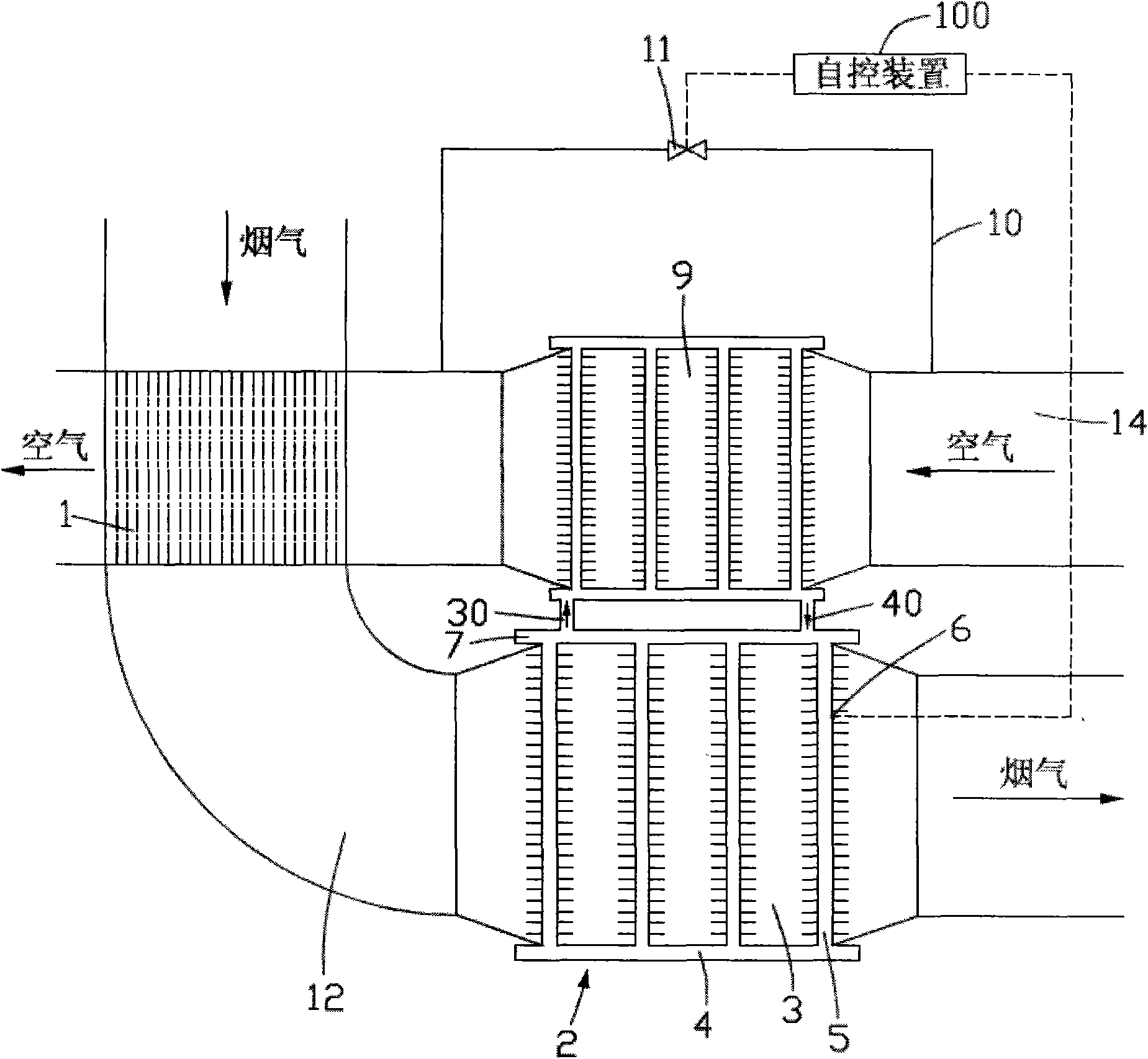
[0014] Please refer to Fig. 1, the flue gas waste heat recovery system of the present invention mainly uses the waste heat of the flue gas at the tail of the boiler to heat the cold air, but is not limited to only using the waste heat of the flue gas at the tail of the boiler to heat the cold air.

[0015] The flue gas waste heat recovery system includes a phase change heat exchanger 2 and an automatic control device 100 installed on the phase change heat exchanger 2 .

[0016] The phase change heat exchanger 2 includes a phase change lower section 3 and a phase change upper section 9 . The phase change lower section 3 communicates with the phase change upper section 9 through a vapor riser 30 and a liquid downcomer 40 . The phase change lower section 3 is arranged in the flue gas channel 12 of an air preheater 1 , so ...


PUM


Abstract

The invention provides a flue-gas waste heat reclaiming system which comprises a phase-change heat exchanger and an automatic control device, wherein the phase-change heat exchanger comprises a phase-change upper section and a phase-change lower section, and the automatic control device is arranged on the phase-change heat exchanger; the phase-change upper section of the phase-change heat exchanger is arranged in an air passage at the front of an inlet of an air preheater, and the phase-change lower section of the phase-change heat exchanger is arranged in a flue-gas passage; and the flow rate of air that enters into the phase-change upper section of the phase-change heat exchanger can be regulated by the automatic control device. On the one hand, the flue-gas waste heat reclaiming system utilizes flue-gas waste heat, instead of a heat source in the traditional air heater, to heat air, thereby saving energy sources; and on the other hand, the flue-gas waste heating reclaiming system regulates the air flow rate by the automatic control device and ensures that the wall temperature of the phase-change heat exchanger is always higher than the flue-gas acid dew point, thereby avoiding the low-temperature corrosion of the air preheater and the phase-change heat exchanger.

Description

technical field [0001] The invention relates to a flue gas waste heat recovery energy-saving system, in particular to a flue gas waste heat recovery system which utilizes the waste heat of flue gas at the tail of a boiler to heat cold air. Background technique [0002] As we all know, if the high-temperature flue gas discharged from the tail flue of the boiler is directly discharged to the atmosphere, it will not only pollute the environment, but also fail to meet the current requirements for boiler energy saving. Therefore, how to effectively utilize the high-temperature flue gas discharged from the tail flue of the boiler to provide an energy-saving and environment-friendly boiler has become a concern of people in the field. [0003] However, while cooling the high-temperature flue gas and effectively utilizing its heat, the problem of low-temperature corrosion in boiler equipment must also be considered. [0004] Since the condensation problem of the low-temperature heat...

Claims


Application Information

Patent Timeline
IPC IPC(8): F23L15/00F28D20/02
CPCF28D15/0266F28D21/001F23L15/045Y02E20/34
Inventor 冯友福杨龙马耀辉王晓鹏
Owner SHENZHEN ZHONGXING KEYANG ENERGY & ENVIRONMENTAL PROTECTION
Why Eureka
Try Eureka