Integrated hydraulically-driven permanent magnet synchronous generator

A permanent magnet synchronous and integrated technology, applied in variable displacement engines, reciprocating piston engines, machines/engines, etc., can solve problems such as external leakage, large weight and space occupation, and unsatisfactory control performance

Inactive Publication Date: 2010-01-27
ZHEJIANG UNIV
View PDF0 Cites 17 Cited by
  • Summary
  • Abstract
  • Description
  • Claims
  • Application Information

AI Technical Summary

Problems solved by technology

At present, the power generation device is generally composed of a separate hydraulic motor, a coupling and a coaxial connection of the generator, but the weight and space occupied by this installation combination are large, and it is not suitable for mobile equipment such as construction machinery
Moreover, hydraulic motors and generators are mechanically driven through coupling

Method used


Image

  • Integrated hydraulically-driven permanent magnet synchronous generator
  • Integrated hydraulically-driven permanent magnet synchronous generator

Examples


Example Embodiment

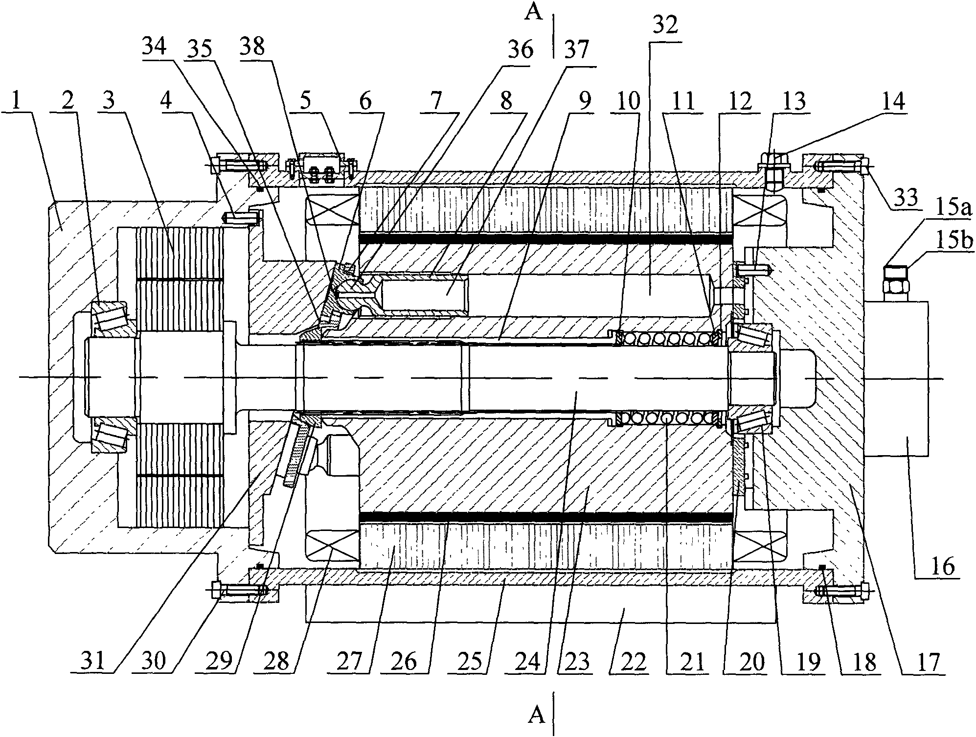
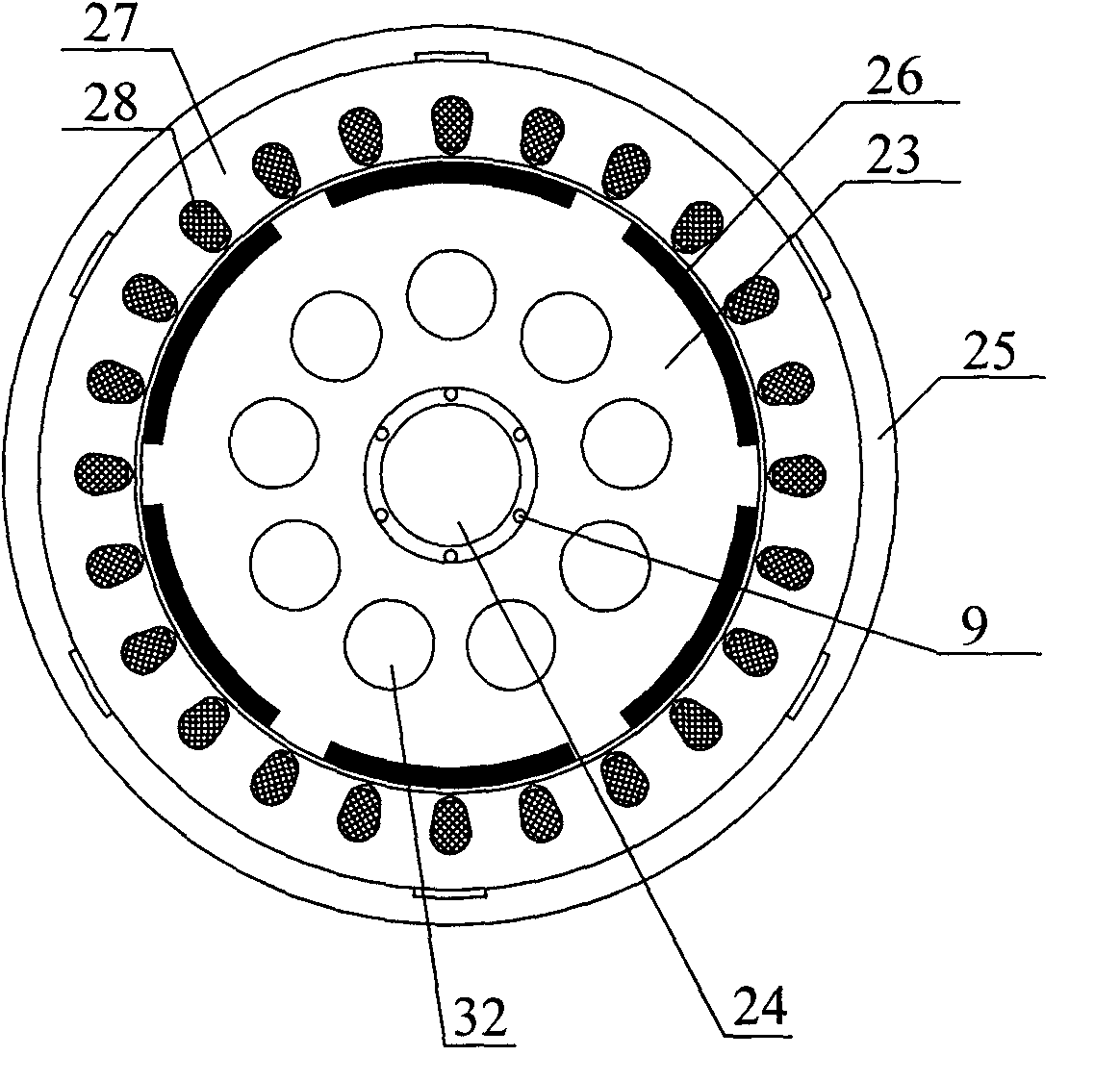
[0017] Figure 1 ~ Figure 2 In combination, an integrated hydraulically driven permanent magnet synchronous generator is provided, which includes a base 22 and a motor housing 25 arranged on the base 22. On both sides of the motor housing 25, a left end cover 1 and a Right end cover 17; the motor housing 25 is provided with a cylinder block 23, a rotating shaft 24, a swash plate 31, an oil distribution plate 20, etc., respectively. A junction box 5 is provided on the motor housing 25, and an oil drain port 14 is also provided on the motor housing 25.

[0018] The left end cover 1 is fixedly connected to the motor housing 25 by screws 30, and a sealing ring 34 is arranged between the left end cover 1 and the motor housing 25; the right end cover 17 is fixedly connected to the motor housing 25 by screws 33, and the right end cover A sealing ring 18 is provided between 17 and the motor housing 25. The right end cover 17 is provided with an oil inlet channel and an oil outlet chann...


PUM


Abstract

The invention discloses an integrated hydraulically-driven permanent magnet synchronous generator which comprises a motor shell (25), a rotating shaft (24), a cylinder body (23), a permanent magnet (26) and a motor stator (27), wherein the right side of the cylinder body (23) is tightly attached to an oil distribution disk (20), and the left side of the cylinder body (23) is provided with an inclined disk (31); a plunger hole (32) is arranged in the cylinder body (23), a plunger (8) positioned in the plunger hole (32) is rotatably connected with a slide shoe (6), and the slide shoe (6) is tightly attached to the inclined disk (31); an oil inlet (15a) on an oil-pass joint block (16), an oil inlet passage in a right end cover (17) and an oil inlet window on the oil distribution disk (20) are communicated in sequence; and an oil outlet (15b) on the oil-pass joint block (16), an oil outlet passage in the right end cover (17) and an oil outlet window on the oil distribution disk (20) are communicated in sequence. The permanent magnet synchronous generator is used for converting hydraulic energy into electric energy.

Description

technical field [0001] The invention relates to hydraulic technology and a permanent magnet synchronous generator, in particular to an integrated conversion device from hydraulic energy to electric energy. Background technique [0002] Using a hydraulic motor to drive a generator to realize the conversion of hydraulic energy to electrical energy can be used in many occasions, such as potential energy recovery of hybrid construction machinery, field power supply, wind power generation, etc. Taking potential energy recovery of hybrid construction machinery as an example, hydraulic motors and generators are installed in the oil return circuit of the system. When the boom is lowered, the return oil back pressure formed by potential energy drives the generator to rotate through the hydraulic motor, and then uses capacitors or batteries to The energy storage device stores the electrical energy generated by the generator, thereby converting the hydraulic energy into electrical ener...

Claims


Application Information

Patent Timeline
IPC IPC(8): H02K7/18H02K11/00F03C1/00H02K5/04H02K11/21
Inventor 王庆丰王滔林添良
Owner ZHEJIANG UNIV
Why Eureka
Try Eureka