

Inverter generator
A technology of inverters and generators, applied in the direction of AC motor control, electrical components, irreversible DC power input conversion to AC power output, etc., can solve problems such as poor power factor, large inrush current, etc., and improve responsiveness , The effect of improving fuel consumption performance
- Summary
- Abstract
- Description
- Claims
- Application Information
AI Technical Summary
Problems solved by technology
Method used
Image

Examples
Embodiment 1
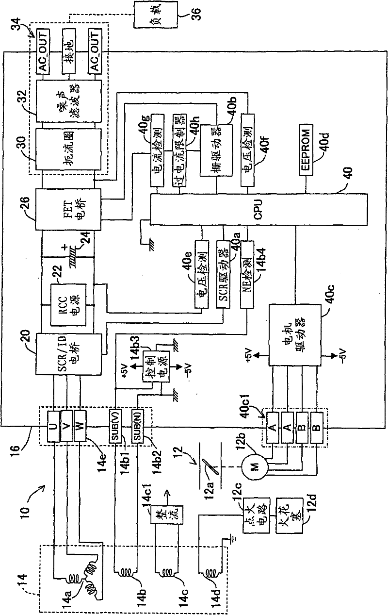
[0031] figure 1 It is a block diagram generally showing the inverter generator according to the first embodiment of the present invention.
[0032] exist figure 1 In the figure, reference numeral 10 denotes an inverter generator, and the generator 10 has a motor (internal combustion engine) 12 and has a rated output of about 2.6 kW (AC 100V, 26A). Engine 12 is an air-cooled engine and is a spark ignition type. Its throttle valve 12a utilizes a throttle motor (actuator) 12b made of a stepper motor to open and close, and utilizes a recoil starter (not shown) to open and close. start.
[0033] A circular stator (not shown) is fixed near the cylinder head of the engine 12, and a three-phase output winding (main phase) consisting of U phase, V phase, and W phase constituting the engine power generation unit 14 is wound around the stator. winding) 14a and three single-phase windings 14b, 14c, 14d.
[0034] A rotor (not shown) serving also as a flywheel of the motor 12 is dispose...
Embodiment 2
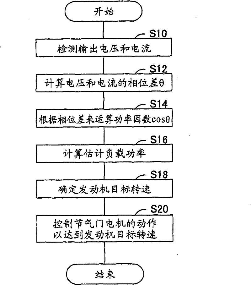
[0064] Figure 6 It is a flowchart showing the operation of the inverter generator according to the second embodiment of the present invention, more specifically, the operation of the CPU 40 thereof. The illustrated program is also executed in each control cycle (step size) defined by the carrier frequency.
[0065] It will be described below. Like the first embodiment, in S100 the voltage and current of the AC output from the inverter 26 are detected, in S102 the phase difference θ of the detected voltage and current is calculated, and in S104 based on the calculated The phase difference to calculate the power factor cosθ.
[0066] Then proceed to S106, and read the output voltage limit amount α. The output voltage limit amount α is in with Figure 6 The processing executed simultaneously in the flow chart is calculated as a negative value. This will be described later.
[0067] Then go to S108, judge whether the output voltage limiting amount α read out is zero, if it i...
PUM
 Abstract
Description
Claims
Application Information