Vapor deposition material and optical thin film obtained from the same
A technology for evaporation materials and optical thin films, which is applied in vacuum evaporation coating, metal material coating process, sputtering coating, etc. Public knowledge and other issues
- Summary
- Abstract
- Description
- Claims
- Application Information
AI Technical Summary
Problems solved by technology
Method used
Image
Examples
Embodiment 1
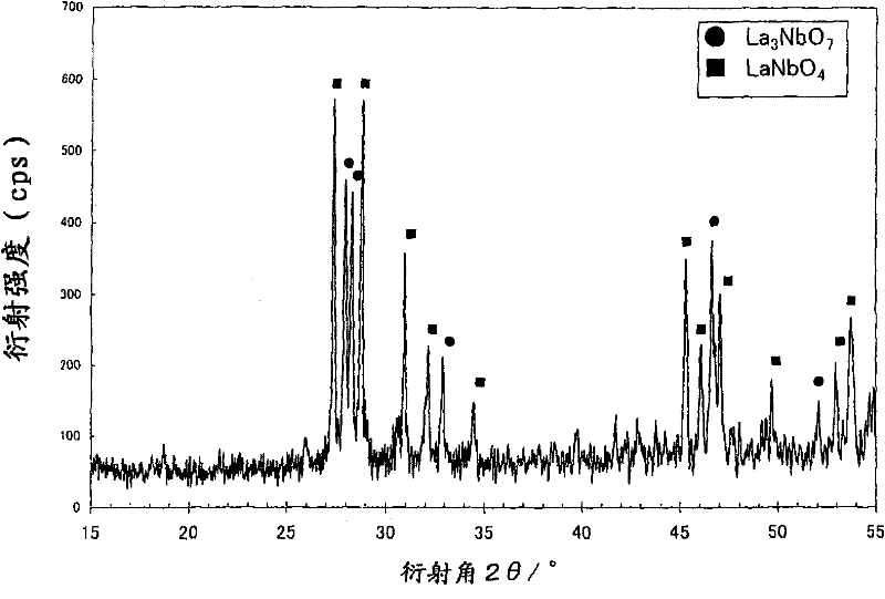
[0051] Mix the powders of niobium (V) oxide and lanthanum (III) oxide at a weight ratio of 32.9:67.1 (the molar ratio of niobium and lanthanum is 37.5:62.5), and granulate the powder mixture into granules of 1 to 3 mm in size. Fired at 1300° C. for 4 hours to obtain a granular vapor deposition material. The material is based on figure 1 The X-ray diffraction pattern shown was identified as La 3 NbO 7 and LaNbO 4 .
[0052] In a commercially available vacuum vapor deposition device, a copper-made Haslina (crucible) filled with the vapor deposition material was installed, and the device was exhausted to 1.0×10 -3 After Pa, the vapor deposition material is melted by electron beam heating to form a molten pool. Next, take the overall pressure to 1.0 x 10 -2Oxygen is introduced in the form of Pa, and only the center of the molten pool is irradiated with electron beams again to generate material vapor. On the substrate pre-set in the device and heated to 300°C, the film is for...
Embodiment 2
[0060] Mix the powders of niobium (V), lanthanum (III) oxide and metallic niobium at a weight ratio of 45.5:46.5:8.0 (the molar ratio of niobium to lanthanum is 60.0:40.0), and form the powder mixture into a sheet of 1 to 3 mm In the form of a tablet, the evaporation material in the form of a tablet is obtained by firing in a vacuum at 1600°C for 4 hours. The material was identified as LaNbO based on the X-ray diffraction pattern 4 and NbO.
[0061] For each film formed by the same method as in Example 1 using this vapor deposition material, the refractive index at a wavelength of 450 nm, the shortest transmission wavelength, and the molar ratio of niobium and lanthanum were determined. The results are shown in Tables 1 and 2. The refractive index and molar ratio are the same regardless of the number of films formed, and the shortest transmission wavelength is 305 nm.
Embodiment 3
[0063] Mix the powders of niobium (V) oxide and lanthanum (III) oxide at a weight ratio of 80.3:19.7 (the molar ratio of niobium to lanthanum is 83.3:16.7), and form the powder mixture into a tablet shape of 1-3mm, and pass through Baking was performed at 1200° C. for 4 hours in the air to obtain a tablet-shaped vapor deposition material. The material was identified as LaNb based on the X-ray diffraction pattern 5 o 14 .
[0064] For each film formed by the same method as in Example 1 using this vapor deposition material, the refractive index at a wavelength of 450 nm, the shortest transmission wavelength, and the molar ratio of niobium and lanthanum were determined. The results are shown in Tables 1 and 2. The refractive index and molar ratio are the same regardless of the number of films formed, and the shortest transmission wavelength is 330 nm.
PUM
| Property | Measurement | Unit |
|---|---|---|
| refractive index | aaaaa | aaaaa |
| refractive index | aaaaa | aaaaa |
| refractive index | aaaaa | aaaaa |
Abstract
Description
Claims
Application Information
 - R&D
- Intellectual Property
- Life Sciences
- Materials
- Tech Scout
- Unparalleled Data Quality
- Higher Quality Content
- 60% Fewer Hallucinations
Browse by: Latest US Patents, China's latest patents, Technical Efficacy Thesaurus, Application Domain, Technology Topic, Popular Technical Reports.
© 2025 PatSnap. All rights reserved.Legal|Privacy policy|Modern Slavery Act Transparency Statement|Sitemap|About US| Contact US: help@patsnap.com


