Method for preventing circularity over tolerance of large gear ring after heat treatment

A ring gear and roundness technology, applied in heat treatment furnaces, heat treatment equipment, heat treatment process control, etc., can solve the problems of increasing process, construction period, energy consumption and labor intensity, complex processing process of ring gear, excessive deformation of parts, etc. Achieve the effect of avoiding waste, shortening the manufacturing cycle and simple operation

Inactive Publication Date: 2010-02-10
DALIAN HUARUI HEAVY IND GROUP
View PDF0 Cites 14 Cited by
  • Summary
  • Abstract
  • Description
  • Claims
  • Application Information

AI Technical Summary

Problems solved by technology

However, due to the influence of too many factors in heat treatment, especially the existence of some accidental factors, there will still be a small number of parts whose deformation exceeds the machining allowance; and the processing procedures of this type of ring gear are complicated, and if scrapped, it will cause huge economic losses. Therefore it is necessary to correct it
[0004] In the literature search of the existing technical documents, it is found that most of the heat treatment correction processes of this type of ring gear currently use the flame hot spot method and the tooling setting method to correct the elliptical deformation of the ring gear, but these two methods require additional processes, construction periods, Energy consumption and labor intensity are not only too complicated for batch heat treatment parts, but also have a long period and high cost

Method used


Image

  • Method for preventing circularity over tolerance of large gear ring after heat treatment
  • Method for preventing circularity over tolerance of large gear ring after heat treatment
  • Method for preventing circularity over tolerance of large gear ring after heat treatment

Examples


Embodiment Construction

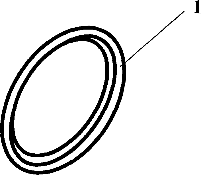
[0027] The present invention will be further described below in conjunction with the accompanying drawings. like Figure 1-3 As shown, a method to prevent the roundness of the large ring gear from being out of tolerance after heat treatment includes the following steps:

[0028] A. Preselect easily deformable ring gear 1;

[0029] B. Perform quenching and tempering treatment on the ring gear 1, that is, quenching + high temperature tempering. After quenching, control the final cooling temperature between the Ms point and the Mz point of the material;

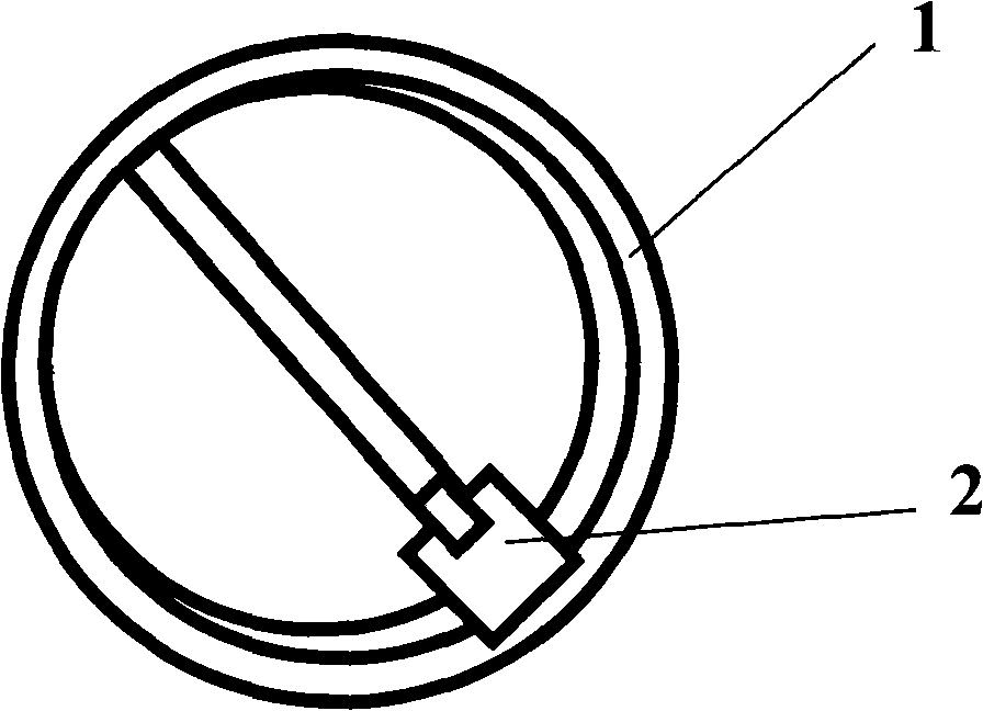
[0030] C. Carry out deformation measurement to ring gear 1;

[0031] D. Use a jack 2 to push the elliptical deformed ring gear 1 at 1 / 4 of the height of the ring gear 1 in the short axis direction of the ring gear 1 until the elliptical deformed ring gear 1 reaches the required size;

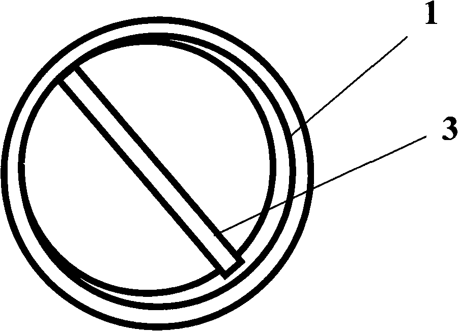
[0032] E. Place the pre-prepared jacking shaft 3 at 3 / 4 of the height of the ring gear 1 near the short axis of the jack 2;

[0033] F, remov...


PUM


Abstract

The invention discloses a method for preventing circularity over tolerance of a large gear ring after heat treatment. The method comprises the following steps: the ellipsoidal deformation gear ring generated after heat treatment quenching is jacked at 1 / 4 height of the gear ring at direction of the minor axis of the gear ring by a lifting jack until the ellipsoidal deformation gear ring is jackedto the required size; a jacking shaft previously prepared is jacked at the 3 / 4 height of the gear ring at direction of the minor axis by the lifting jack; the lifting jack is removed; normal temperingtreatment is carried out on the gear ring with the jacking shaft in a furnace; and the gear ring after tempering is cooled down to room temperature, the jacking shaft is removed to end the deformation correction. In the invention, only the steps for measuring deformation and installing the jacking shaft are added in the original heat treatment process flow, and the success rate for correction canbe up to 100%. The two steps both have no influence on the original heat treatment process; therefore, the invention also realizes the purposes of no extra addition of working procedure, working period, energy consumption and labor intensity, thereby avoiding the occurrence of waste products and lowering the manufacturing cost of products.

Description

technical field [0001] The invention relates to a metal material heat treatment technology, in particular to a method for preventing the roundness of a large ring gear from being out of tolerance after heat treatment. Background technique [0002] Quenching and tempering treatment in the parts heat treatment process usually refers to heating the steel parts to a temperature above the austenitization temperature Ac3 or Ac1 point, keeping it for a certain period of time, and then cooling at the critical cooling rate to obtain a martensite structure, Then carry out the heat treatment process of high temperature tempering. Due to the inhomogeneity of the temperature and structural changes of the parts interface during heating and cooling, as well as the gravity and clamping force of the parts, under the action of internal stress and external force, the parts will be more or less distorted after heat treatment. Two kinds of deformation often occur in quenching and tempering trea...

Claims


Application Information

Patent Timeline
IPC IPC(8): C21D9/32C21D1/25C21D11/00
Inventor 王建华段惠刚孙亚芝王永君孙斌韩华杨磊张家亮
Owner DALIAN HUARUI HEAVY IND GROUP
Why Eureka
Try Eureka