
Separate combination type air heat regenerator

A technology of air heat and recycler, applied in indirect heat exchangers, using air flow as shielding, space heating and ventilation, etc., can solve the problems of not making full use of environmental conditions, increasing high-quality energy consumption, and high-quality energy waste, etc. problems, to achieve excellent heat transfer efficiency, significant energy-saving effect, and energy-saving effect

Active Publication Date: 2010-02-10
HEFEI GENERAL ENVIRONMENT CONTROL TECH
View PDF0 Cites 4 Cited by
  • Summary
  • Abstract
  • Description
  • Claims
  • Application Information

AI Technical Summary

Problems solved by technology

[0002] There are a large number of cooling and heating processes in a large number of industrial production systems, test and detection systems, etc., especially the two test environments of various refrigeration and air-conditioning laboratories need to cool and heat the air in the two environments at the same time. These cooling and heating processes are not comprehensively designed and utilized in many occasions, resulting in a large amount of waste of high-quality energy; on the other hand, the cooling process does not make full use of environmental conditions for cooling, which also increases the consumption of a large amount of high-quality energy
The traditional environmental treatment methods used in these air-conditioning systems consume a lot of energy. One of the characteristics of energy consumption is that the system has heat supply (cold) and heat exhaust (cold) processes at the same time. If the heat to be discharged ( The cold) is transferred to the place where heat (cold) is needed, that is, heat energy recovery can effectively use energy

Method used


Image

  • Separate combination type air heat regenerator
  • Separate combination type air heat regenerator
  • Separate combination type air heat regenerator

Examples


Embodiment 1

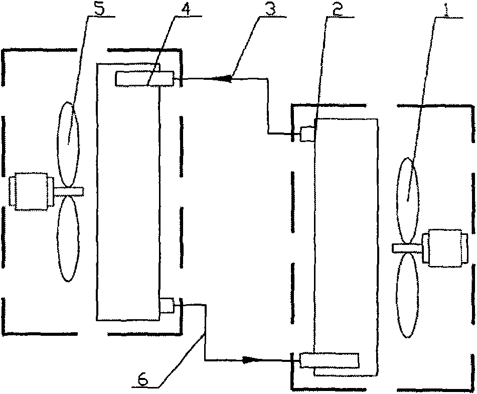
[0029] see figure 1 , the separated and combined air heat recovery device includes two heat exchangers, one is the hot side heat exchanger 2, and the other is the cold side heat exchanger 4; A cold-side fan 5 is arranged outside the heat exchanger 4 .

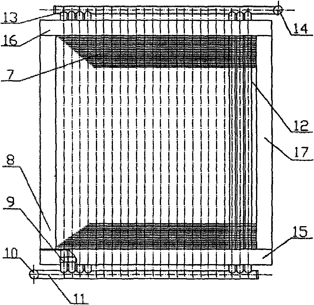
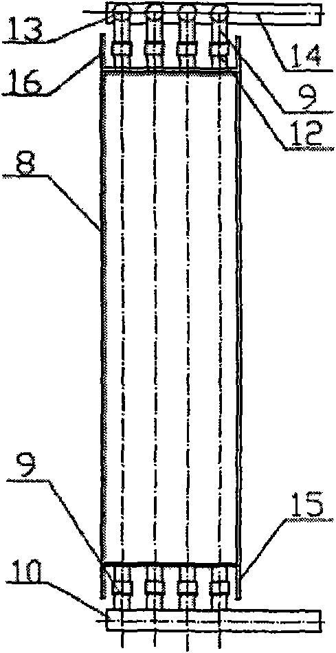
[0030] see figure 2 , image 3 and Figure 4 , the heat exchanger includes four rows of heat exchange tubes, and each row of heat exchange tubes includes more than ten heat exchange tubes; In the frame-type frame, the two ends of each heat exchange tube 12 extend to the outside of the bottom plate 15 and the top plate 16 respectively; Gas manifold 13, one end of four gas manifolds 13 is connected with inlet or outlet pipe 14, one end of inlet or outlet pipe 14 is a closed end, and the other end is an inlet or outlet; each row of heat exchange tubes The lower extension ends of the heat exchange tubes 12 are respectively connected to the liquid header pipe 11 through the connecting pipe 9, and one end of the four liquid hea...

Embodiment 2

[0037] see Figure 5 , Figure 6 and Figure 7 One end of the four gas collection pipes 13 is connected to two inlet or outlet pipes 14 respectively, one end of the two inlet or outlet pipes 14 is a closed end, and the other end is an inlet or outlet end; the four liquid collection pipes One end of the manifold 11 is connected to two outlet or inlet pipes 10 in pairs; one end of the two outlet or inlet pipes 10 is a closed end, and the other end is an outlet or inlet end.

[0038] The medium liquid level in the hot side heat exchanger is higher than the medium liquid level in the cold side heat exchanger, and the height difference is 20 mm.

[0039] Others are with embodiment 1.

Embodiment 3

[0041] see Figure 8 , Figure 9 and Figure 10 , the other ends of the four gas manifolds 13 are all gas inlet or outlet ends; the other ends of the four liquid manifolds 11 are all outlet or liquid inlet ends.

[0042] The medium liquid level in the hot side heat exchanger is higher than the medium liquid level in the cold side heat exchanger, with a height difference of 10mm.

[0043] Others are with embodiment 1.


PUM


Abstract

The invention relates to a separate combination type air heat regenerator, solving the recycling problem of air heat (cryogenic) energy in an air conditioner system. The invention comprises a hot sideheat exchanger, a cold side heat exchanger, a hot side fan and a cold side fan; the heat exchangers comprise more than one row of heat exchanging pipes, each row comprises more than ten heat exchanging pipes; the upper extending-outwards end of each heat exchanging pipe on each row is respectively communicated with an air converging pipe through a connecting pipe, and one end of four air converging pipes is an air inlet end or an air outlet end; the lower extending-outwards end of each heat exchanging pipe on each row is respectively communicated with a liquid converging pipe through a connecting pipe, and one end of four liquid converging pipes is a liquid outlet end or a liquid inlet end. The invention is a high effective air heat exchanger, as long as the temperature difference of coldair flow and hot air flow exceeds 3 DEG C the energy can be recycled, and with the increase of the temperature difference of cold air flow and hot air flow the energy saving effect grows more obvious. The invention can be widely applied in conditions such as air cooling, air heating, air backheating and the like in refrigeration air conditioner laboratories.

Description

technical field [0001] The invention relates to an air heat exchanger, in particular to a separated and combined air heat recovery device. Background technique [0002] There are a large number of cooling and heating processes in a large number of industrial production systems, test and detection systems, etc., especially the two test environments of various refrigeration and air-conditioning laboratories need to cool and heat the air in the two environments at the same time. These cooling and heating processes are not comprehensively designed and utilized in many occasions, resulting in a large amount of waste of high-quality energy; on the other hand, the cooling process does not make full use of environmental conditions for cooling, which also increases the consumption of a large amount of high-quality energy. The traditional environmental treatment methods used in these air-conditioning systems consume a lot of energy. One of the characteristics of energy consumption is ...

Claims


Application Information

Patent Timeline
Patent Type & Authority Applications(China)
IPC IPC(8): F24F12/00F28D15/02
Inventor 史敏张秀平程立权王磊
Owner HEFEI GENERAL ENVIRONMENT CONTROL TECH
Learn More