Eureka AIR delivers breakthrough ideas for toughest innovation challenges, trusted by R&D personnel around the world.

Zoom lens system

A technology of zoom lens and compensation lens, which is applied in the field of zoom lens system, can solve problems such as unfavorable zoom lens system volume, complicated mechanical drive device, troublesome design and manufacture, etc., and achieves the effects of simple manufacture, simplified drive transmission mechanism, and convenient portability

Active Publication Date: 2012-06-13
THE HONG KONG POLYTECHNIC UNIV
View PDF4 Cites 1 Cited by
  • Summary
  • Abstract
  • Description
  • Claims
  • Application Information

AI Technical Summary

Problems solved by technology

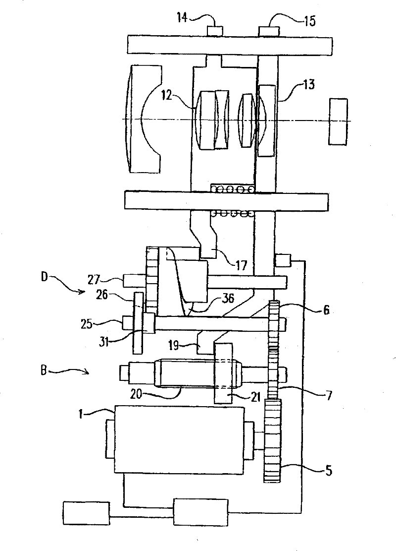
[0003] It can be seen from the structure of the above-mentioned driving device that the mechanical driving device in the current zoom lens system is very complicated, and it is driven by a power source through two sets of transmission mechanisms to drive the zoom driving device and the compensation driving device respectively.
Its structure includes gears, intermittent transmission mechanism, lead screw and other transmission parts that cooperate with each other, which not only has high manufacturing cost, but also takes up a lot of space, which is not conducive to reducing the volume of the zoom lens system. Ensure high transmission accuracy, otherwise it will greatly affect the imaging quality
In addition, if the optical parameters of the zoom system change, the original mechanical drive device cannot continue to be used, and a suitable mechanical drive device needs to be redesigned, which is not only troublesome in design and manufacture, but also further increases the cost

Method used


Image

  • Zoom lens system
  • Zoom lens system
  • Zoom lens system

Examples


Embodiment Construction

[0027] Specific embodiments of the present invention will be described in detail below. It should be noted that the embodiments described here are for illustration only, and are not intended to limit the present invention.

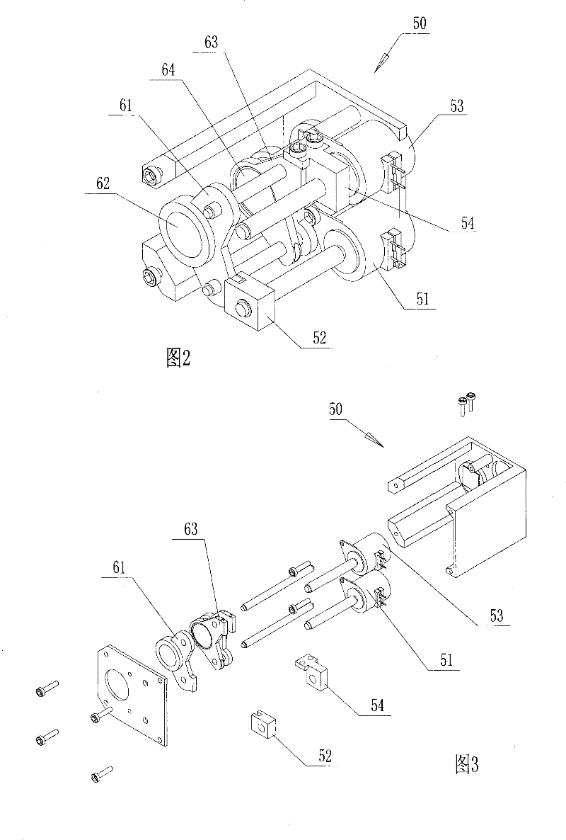
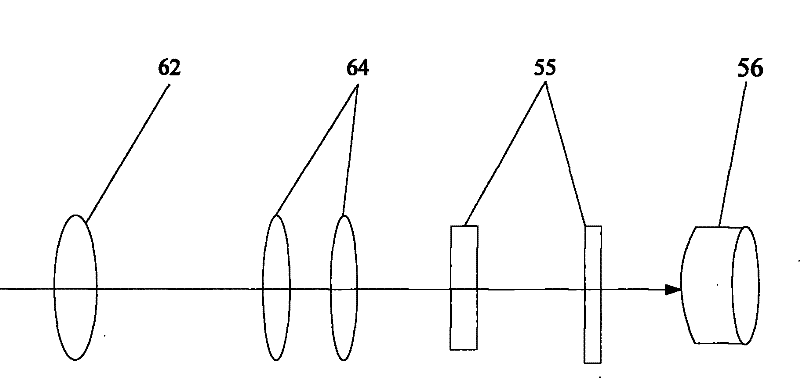
[0028] Such as figure 2 , image 3 and Figure 4 As shown, the structure of the zoom lens system of the present invention includes a zoom unit installed in a housing 50, an imaging element 56 (see Figure 4 ) a compensation unit 64 and a drive transmission mechanism for compensating aberrations. Two parallel mounting shafts are fixed on two opposite side plates of the housing 50 . The zoom unit includes a zoom lens holding frame 61 slidably installed on two installation shafts and a zoom lens group 62 installed in the holding frame 61 . The compensation unit includes a compensation lens holding frame 63 slidably installed on two installation shafts and a compensation lens group 64 installed in the holding frame 63 . Wherein the zoom lens group 62 an...


PUM


Abstract

The invention provides a zoom lens system, which comprises a zooming unit, a compensating unit and an imaging unit arranged on a same optical axis in turn, a driving transmission mechanism and a micro-processing control unit, wherein the driving transmission mechanism comprises a zooming stepping motor and a compensating stepping motor. The zooming unit is arranged on an output shaft of the zooming stepping motor through a driving piece; the compensating unit is arranged on an output shaft of the compensating stepping motor through the driving piece; and the micro-processing control unit adjusts the distance between the compensating unit driven by the compensating stepping motor and the imaging unit according to the distance changes between the zooming unit driven by the zooming stepping motor and the imaging unit. The zoom lens system has the advantages of compact structure, small volume, simple manufacturing, low cost, economization and portability.

Description

technical field [0001] The invention relates to a zoom lens system, in particular to a zoom lens system for a mobile phone, a digital camera or a video camera with a zoom function. Background technique [0002] The zoom lens system is one of the important components of the system with zoom function. The structure of the existing zoom lens system generally includes a zoom unit, a zoom driving device, a compensation unit, a compensation driving device and the like. Wherein the zoom unit includes a first lens group with positive refraction, a second lens group with negative refraction and a third lens group with positive refraction arranged on the same optical axis from the object side to the image side in sequence, in some lens systems The third lens group may not be provided in the lens; the compensation unit is a fourth lens group with positive refraction arranged between the third lens group and the image side. When the magnification is changed from the wide-angle state w...

Claims


Application Information

Patent Timeline
Patent Type & Authority Patents(China)
IPC IPC(8): G02B7/04G03B13/34
CPCG02B7/102
Inventor 杜雪张志辉李荣彬蒋金波王文奎
Owner THE HONG KONG POLYTECHNIC UNIV
Why Eureka
Eureka Blog
Learn More