Chip cooling device

A cooling device and chip technology, applied in electrical components, electrical solid devices, circuits, etc., can solve problems affecting chip integration and packaging, occupation, large space, etc., and achieve small contact thermal resistance, uniform temperature distribution, and high critical heat flow. Effects of Density Values

Inactive Publication Date: 2010-02-10
ZHEJIANG UNIV
View PDF0 Cites 19 Cited by
  • Summary
  • Abstract
  • Description
  • Claims
  • Application Information

AI Technical Summary

Problems solved by technology

Since the convective heat transfer efficiency of liquid is higher than that of gas, an immersion liquid cooling device has appeared at present. The upper surface of the chip is in direct contact with the heat sink, and the other side of the heat sink is immersed in water, and the liquid circulates under the action of an external pump. , so as to transport the heat of the chip to the atmospheric environment. Although this device has a good cooling effect, it takes up a large space and affects the subsequent integration and packaging of the chip.

Method used


Image

  • Chip cooling device
  • Chip cooling device

Examples


Embodiment Construction

[0019] The chip cooling device of the present invention will be described below with reference to the accompanying drawings.

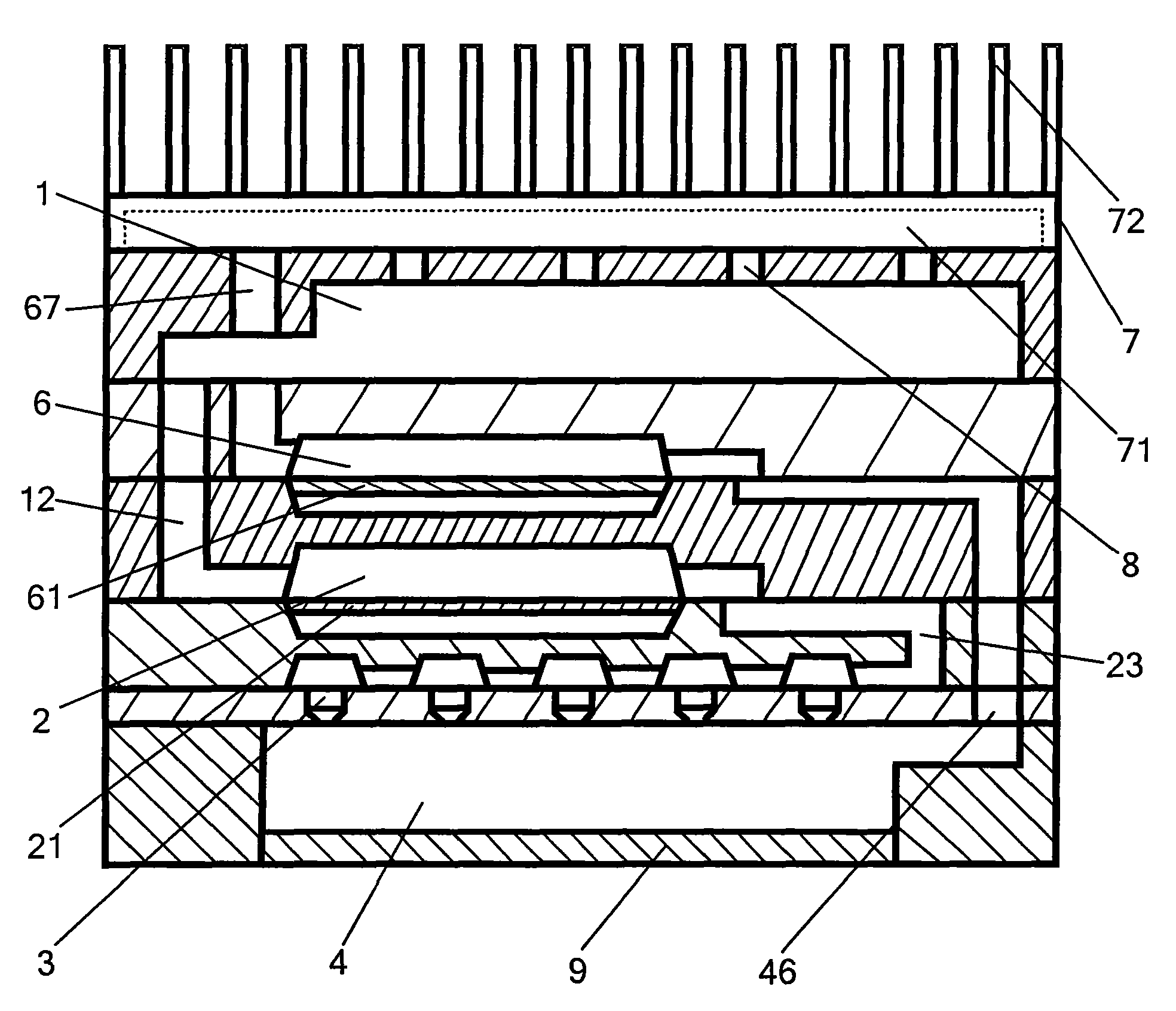
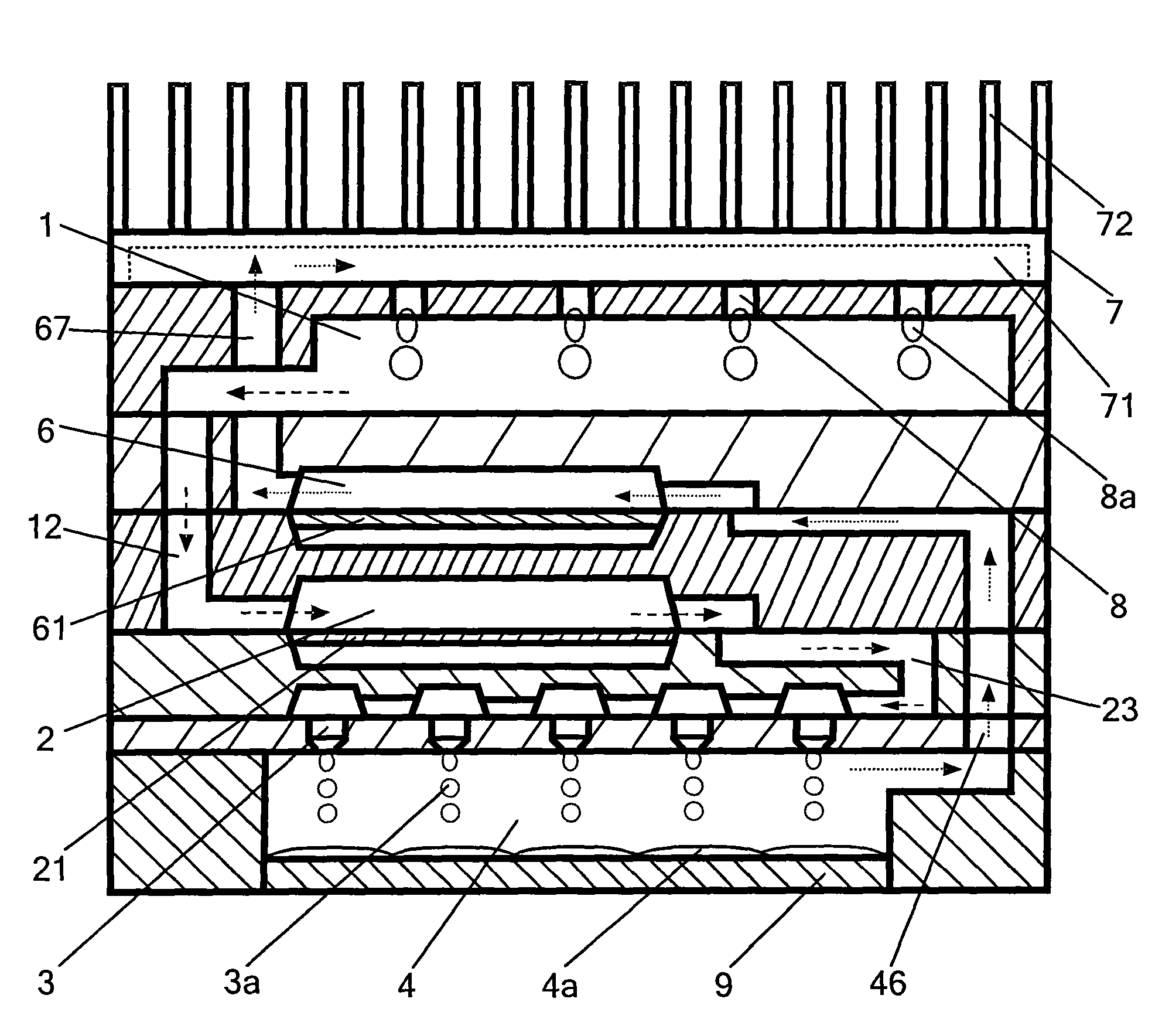
[0020] See figure 1 , figure 2 ,in figure 2 The arrow symbol in -→ represents the flow direction of liquid coolant, and the arrow symbol Indicates the direction of flow of gaseous coolant. The chip cooling device of the present invention mainly includes a cooling liquid pool 1, a first micro-channel 12, a first micro-pump 2, a second micro-channel 23, a micro-nozzle 3, a cooling chamber 4, a third micro-channel 46, a second micro-channel Pump 6 , fourth microchannel 67 , condenser 7 , and micropore 8 . The cooling liquid pool 1 stores cooling liquid (not shown in the figure). Coolant is required to have good thermophysical properties, electrical properties, corrosion inhibition, safety and stability for chips. Thermophysical properties include suitable boiling point temperature, higher latent heat of vaporization and specific heat, higher dens...


PUM


Abstract

The invention discloses a chip cooling device which comprises a cooling room positioned at the bottom of the device and matched with the chip, a cooling liquid pond stored with cooling liquid, a firstmicro channel, a first micro pump, a second micro channel, a micro nozzle, a third micro channel, a second micro pump, a fourth micro channel, a condenser and a micropore, wherein one end of the first micro pump is communicated with the cooling liquid pond by the first micro channel and the other end is communicated with the micro nozzle by the second micro channel; the micro nozzle is arranged above the cooling room and communicated with the cooling room; one end of the second micro pump is communicated with the cooling room by the third micro channel and the other end is communicated with the condenser by the fourth micro channel; the condenser is positioned above the cooling liquid pond and a condensing channel is arranged in the interior of the condenser; and a radiating fin is arranged on the top of the condensing channel which is communicated with the cooling liquid pond by the micropore. The chip cooling device has small volume, high heat dissipation efficiency, very high controllability and working flexibility and can meet the cooling requirements of the chip in different working conditions.

Description

technical field [0001] The invention relates to a chip cooling device, in particular to a chip cooling device for cooling high-density and high-power chips using micro-electromechanical system technology. Background technique [0002] The current chip cooling devices mostly use external heat sinks and fans. These two chip cooling devices remove the heat from the chip through convective heat transfer of the air. Higher, take the fan cooling device used by the computer CPU as an example. When the fan blades rotate at a speed of up to 4000r / min, the temperature of the CPU can be basically prevented from being too high, but the device is very noisy, and the heat dissipation capacity has reached air convection heat transfer limit. With the rapid development of microelectronics technology, factors such as more complex integrated functions of a single chip, rapid increase of clock frequency, thinner package, reduced pin pitch of package, and reduced number of pins of package lead ...

Claims


Application Information

Patent Timeline
Patent Type & Authority Applications(China)
IPC IPC(8): H01L23/427H01L23/367H01L21/48
Inventor 应济李俊徐亮林谢昭
Owner ZHEJIANG UNIV
Why Eureka
Try Eureka