Petrol engine supercharger bypass valve

A supercharger and bypass valve technology, which is applied in the direction of machines/engines, valve details, valve devices, etc., can solve the problems of material, structure, and reliability that cannot meet the requirements, synchronous wear of pin 1 and rocker arm 2, and low-speed engine torque Poor and other problems, to avoid free rotation, improve reliability, improve the effect of flatness

Active Publication Date: 2010-02-17
JAPHL POWERTRAIN SYST
View PDF0 Cites 15 Cited by
  • Summary
  • Abstract
  • Description
  • Claims
  • Application Information

AI Technical Summary

Problems solved by technology

The early exhaust gas turbocharger did not have a waste gas bypass device. In order to ensure that the speed of the turbocharger and the exhaust back pressure of the engine would not be too high when the engine was at high speed, the volute flow path was usually made larger. The disadvantage of this structure Yes: When the engine is at low speed, the exhaust gas does less work on the turbine, the speed of the impeller is low, and the air flow is also small, so the low-speed torque of the engine is poor
After long-term operation, the pin 1 and the rocker arm 2 will wear out synchronously, the

Method used


Image

  • Petrol engine supercharger bypass valve
  • Petrol engine supercharger bypass valve
  • Petrol engine supercharger bypass valve

Examples


Embodiment 1

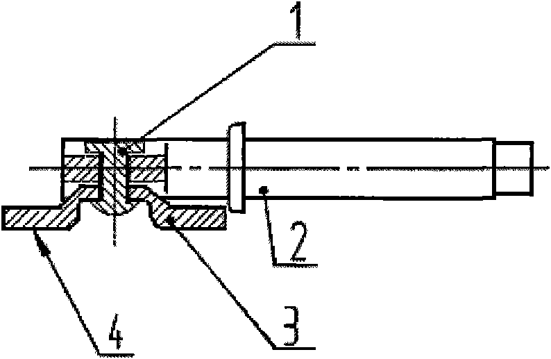
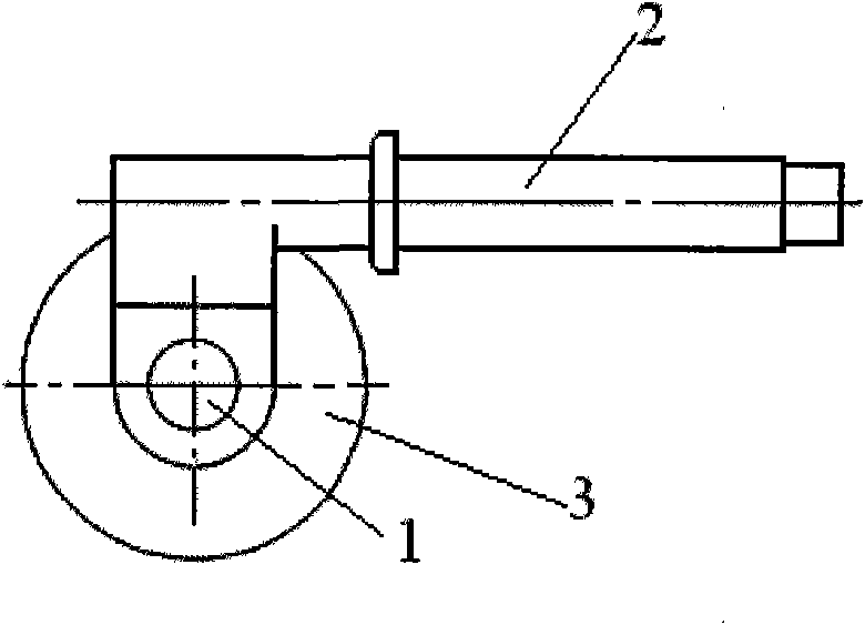
[0038] Such as image 3 , Figure 4 with Figure 5 As shown, the cross-section of the valve connection boss 9 in the present invention is a waist circle, and the shape of the rocker arm connection hole 10 is matched with the waist circle.

[0039] Such as image 3As shown, the rocker arm 2 and the bypass valve 3 are made of new high-temperature-resistant stainless steel investment casting precision casting, and the gasket 5 is directly stamped from a new stainless steel plate, which ensures that the material can withstand the high temperature environment of 950 ° C ~ 1050 ° C from the material. adaptability. Finally, it is welded by argon arc welding.

[0040] The joint between the rocker arm 2 and the bypass valve 3 is round and loose. Therefore, the bypass valve cannot rotate freely. Through this reasonable anti-rotation connection structure design, it is ensured that the bypass valve 3 cannot freely rotate on the rocker arm 2, and wear is reduced.

[0041] The bonding...

Embodiment 2

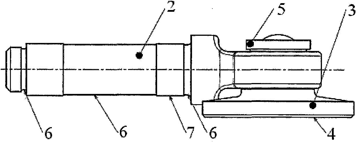
[0043] Such as Image 6 , Figure 7 with Figure 8 As shown, the cross section of the valve connection boss 9 of the present invention is circular, the rocker arm connection hole 10 is a round hole, and matches with the valve connection boss 9, and the bypass valve 3 and On one side connected with the valve connection boss 9, an anti-rotation pin 8 is provided, and the side surfaces of the anti-rotation pin 8 and the side surfaces of the rocker arm 2 are attached to each other.

[0044] Such as Image 6 As shown, the rocker arm 2 and the bypass valve 3 are made of new high-temperature-resistant stainless steel investment casting precision casting, and the gasket 5 is directly stamped from a new stainless steel plate, which ensures that the material can withstand the high temperature environment of 950 ° C ~ 1050 ° C from the material. adaptability. Finally, it is welded by argon arc welding.

[0045] An anti-rotation pin 8 is cast on the bypass valve 3 . The joint betwee...


PUM


Abstract

The invention discloses a petrol engine supercharger bypass valve which comprises a bypass valve (3) and a rocking arm (2), wherein a valve connecting lug boss (9) is arranged on the bypass valve (3);the valve connecting lug boss (9) and the bypass valve (3) are in an integral structure; the end part of the rocking arm (2) is bent and pressed into a flat shape; a rocking arm connecting hole (10)is arranged on the flat shape structure; and the bypass valve (3) is connected with the rocking arm (2) by the match of the valve connecting lug boss (9) and the rocking arm connecting hole (10). Therocking arm and the bypass valve are formed by the precision casting of a novel stainless steel material melting die, and a spacer is formed by stamping novel stainless steel, therefore, the creep resistance at high temperature is ensured, the planeness of a volute attaching surface and the utilization of the supercharger on waste gas energy when an engine is at low speed are improved, the rotating freedom degree of the bypass valve is limited, the valve is prevented from generating free rotation by waste gas disturbance, the abrasion is reduced and the requirement for a high-performance petrol engine is met.

Description

technical field [0001] The invention belongs to the technical field of automobile construction, and relates to the structure of a gasoline engine supercharger, more specifically, the invention relates to a gasoline engine supercharger bypass valve. Background technique [0002] At present, engine supercharging turbine technology has been widely used. This technology usually installs an exhaust gas turbocharger on the engine, and the exhaust gas drives the turbine to rotate, driving the coaxial impeller to rotate, so that high-pressure gas enters the engine cylinder. Due to the increased air density for combustion, that is, the increased air mass, the corresponding fuel supply is more, so that the engine generates more power. The early exhaust gas turbocharger did not have a waste gas bypass device. In order to ensure that the speed of the turbocharger and the exhaust back pressure of the engine would not be too high when the engine was at high speed, the volute flow path was...

Claims


Application Information

Patent Timeline
IPC IPC(8): F02B37/22F02B37/18F16K31/44
CPCY02T10/144Y02T10/12
Inventor 周俊施法佳范礼项青新
Owner JAPHL POWERTRAIN SYST
Why Eureka
Try Eureka