

Method and device for self-recovery current limiting and circuit breaking by using conductive fluid and magnetic fluid
A technology of conductive fluid and magnetic fluid, which is applied in the direction of protection against overcurrent, relays and circuits using electrodynamic effects, etc., can solve problems such as gas injection, failure to be well resolved, and aging of solid electrodes, and achieve The effect of limiting arc generation
- Summary
- Abstract
- Description
- Claims
- Application Information
AI Technical Summary
Problems solved by technology
Method used
Image

Examples
Embodiment 1
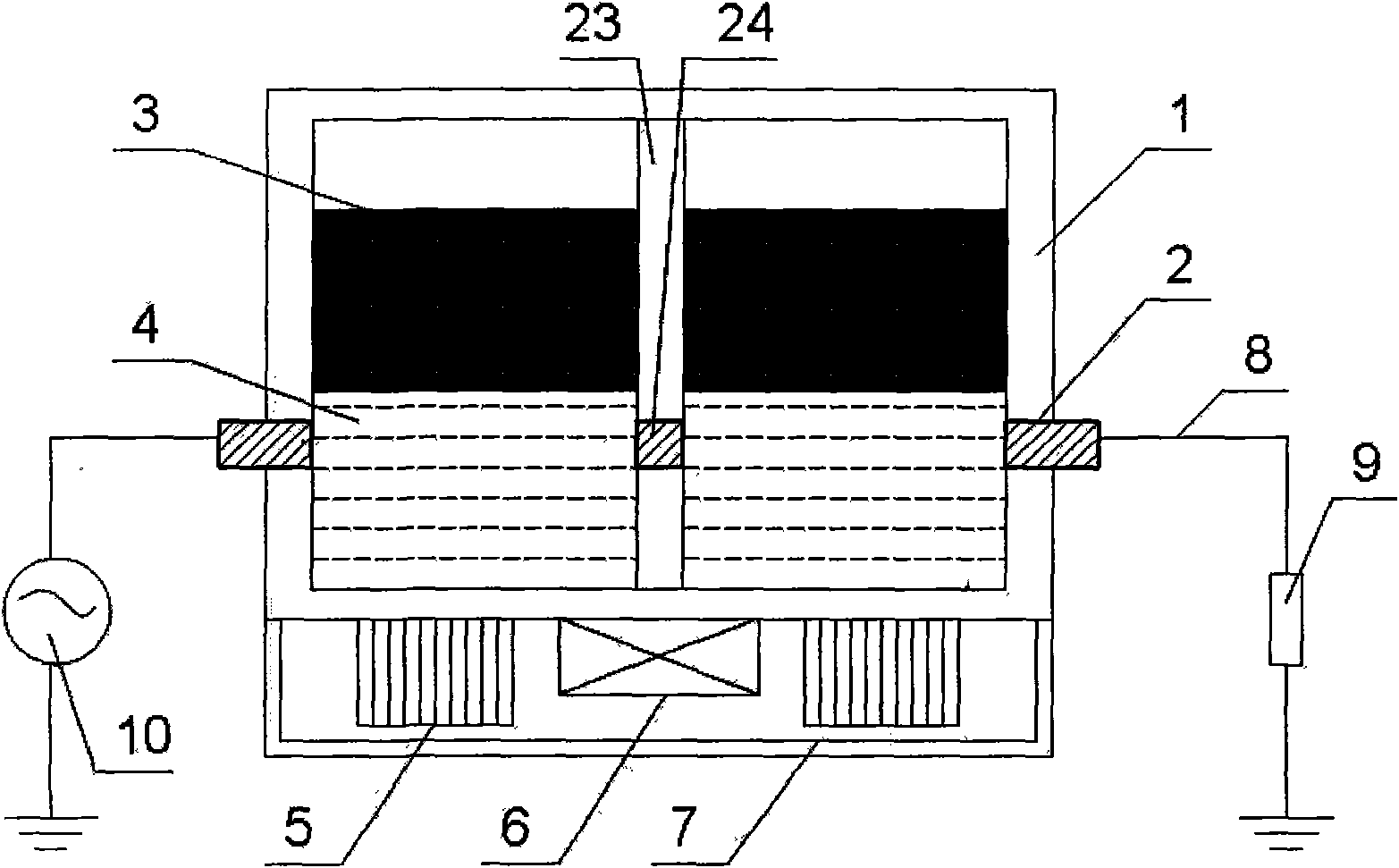
[0116] A self-resetting current-limiting circuit breaker using conductive fluid and magnetic fluid such as figure 1 As shown, the magnetic field generating device 6 adopts a third connection form as shown in FIG. The packaging shell 1 is made of ceramic material, and forms two identical airtight cavities with the separator 23, the solid-state electrode terminal 2, and the solid-state electrode terminal 24, and the size of each airtight cavity (length×width×height) is 40mm×20mm× 20mm, using MF03 magnetic fluid 3 produced by Beijing Shenran Magnetic Fluid Technology Co., Ltd., with a density of 1320kg / m 3 , the saturation magnetization is 450GS, liquid metal gallium is used as the conductive fluid 4, and its density is 5907kg / m 3 , inject equal volumes of liquid metal gallium and magnetic fluid into the closed cavity respectively, with the magnetic fluid on the top and gallium on the bottom, the total volume of the magnetic fluid and liquid metal gallium accounts for 90% of the...
Embodiment 2
[0120] A self-resetting current-limiting circuit breaker using conductive fluid and magnetic fluid such as figure 1 As shown, the current limiting circuit breaking device is used in combination with the voltage loss protection device, as shown in Figure 4(c), and the magnetic field generating device 6 adopts the second connection form, as shown in Figure 3(b), in this embodiment An electromagnet with a maximum magnetic induction intensity of 0.1T is selected as the magnetic field generating device 6 . The controlled circuit 8 is used as the primary coil of the transformer device 22, and the circuit where the magnetic field generator 6 is located is used as the secondary coil of the transformer device 22. The connection form of the potentiometer 11 and the fixed value resistor 12 is shown in Figure 3(b). The packaging shell 1 is made of glass material, and forms two identical airtight cavities with the separator 23, the solid-state electrode terminal 2, and the solid-state elec...
Embodiment 3
[0124] A self-resetting current-limiting circuit breaker using conductive fluid and magnetic fluid such as figure 1 As shown, the current limiting circuit breaking device is used in combination with the voltage loss protection device, as shown in Figure 4(c), the magnetic field generating device 6 adopts the first connection form, as shown in Figure 3(a), in this embodiment An electromagnet with a maximum magnetic induction of 0.3T is selected as the magnetic field generator 6, and the connection form of the potentiometer 11 is shown in Figure 3(a). The packaging shell 1 is made of epoxy resin material, and forms two identical airtight cavities with the separator 23, the solid electrode terminal 2, and the solid electrode terminal 24, and the size of each airtight cavity (length×width×height) is 40mm× 20mm×20mm, using MF03 magnetic fluid 3 produced by Beijing Shenran Magnetic Fluid Technology Co., Ltd., using liquid metal mercury as the conductive fluid 4, and its density is 1...
PUM
| Property | Measurement | Unit |
|---|---|---|
| Density | aaaaa | aaaaa |
| Saturation magnetization | aaaaa | aaaaa |
| Density | aaaaa | aaaaa |
Abstract
Description
Claims
Application Information