Working device, adhesive tape applying device, and method of adding tape member
A technology of laminating device and joining device, applied in the directions of adhesives, electrical components, sending objects, etc., can solve the problems of transportation failure, increased burden, complicated device structure, etc., achieve smooth belt transfer, reduce management burden, and simple device structure. Effect
- Summary
- Abstract
- Description
- Claims
- Application Information
AI Technical Summary
Problems solved by technology
Method used
Image

Examples
no. 1 Embodiment approach
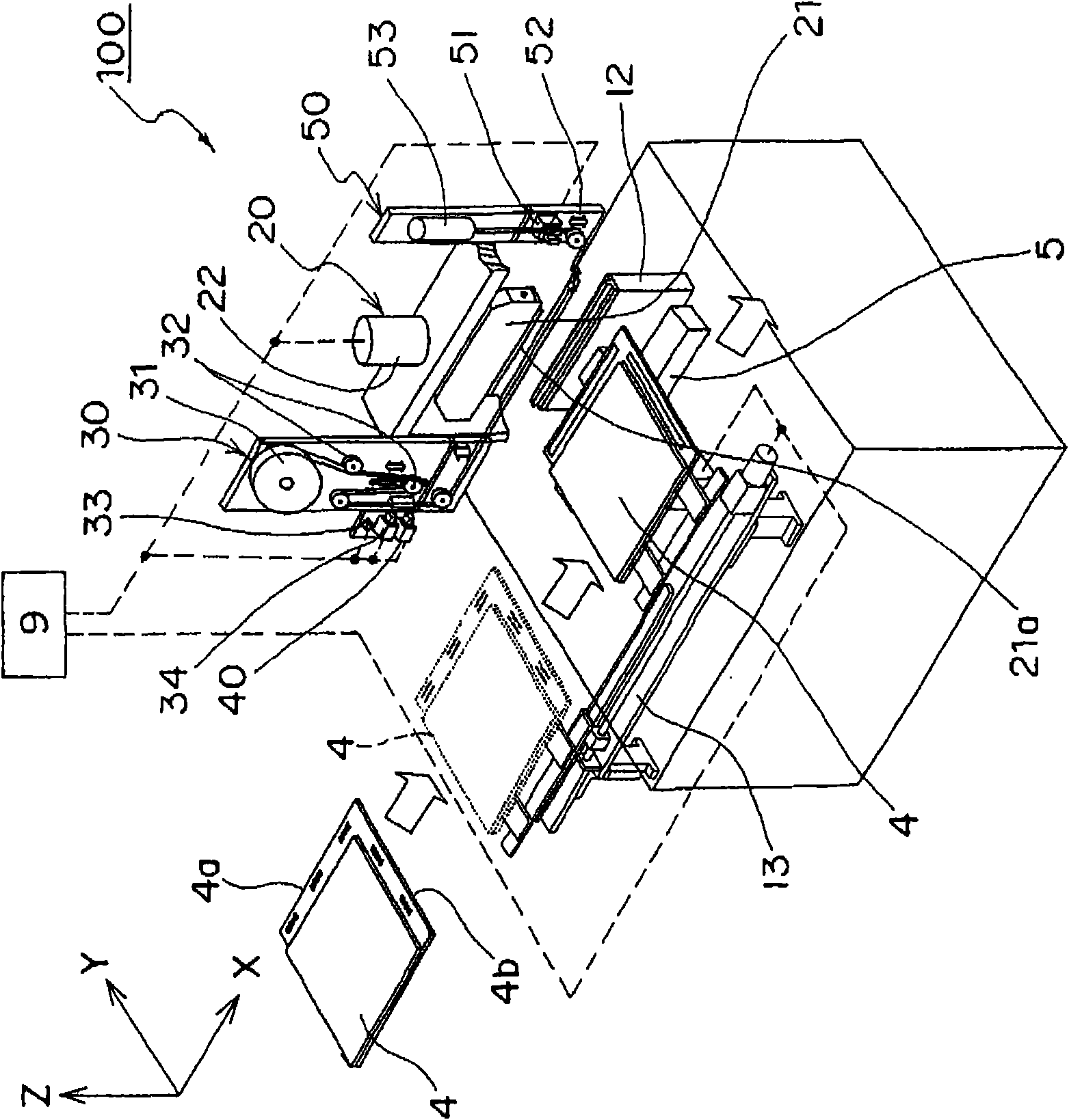
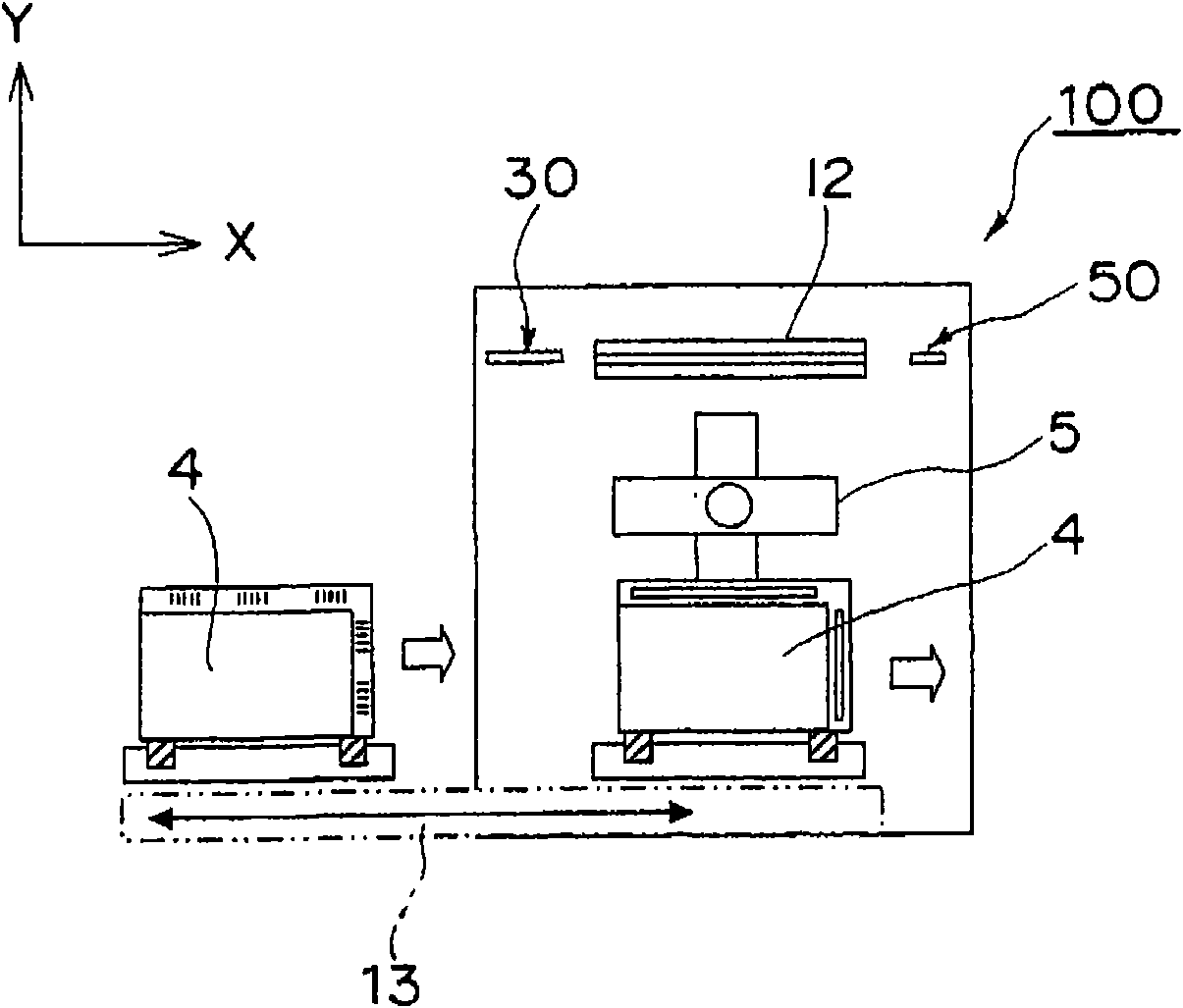
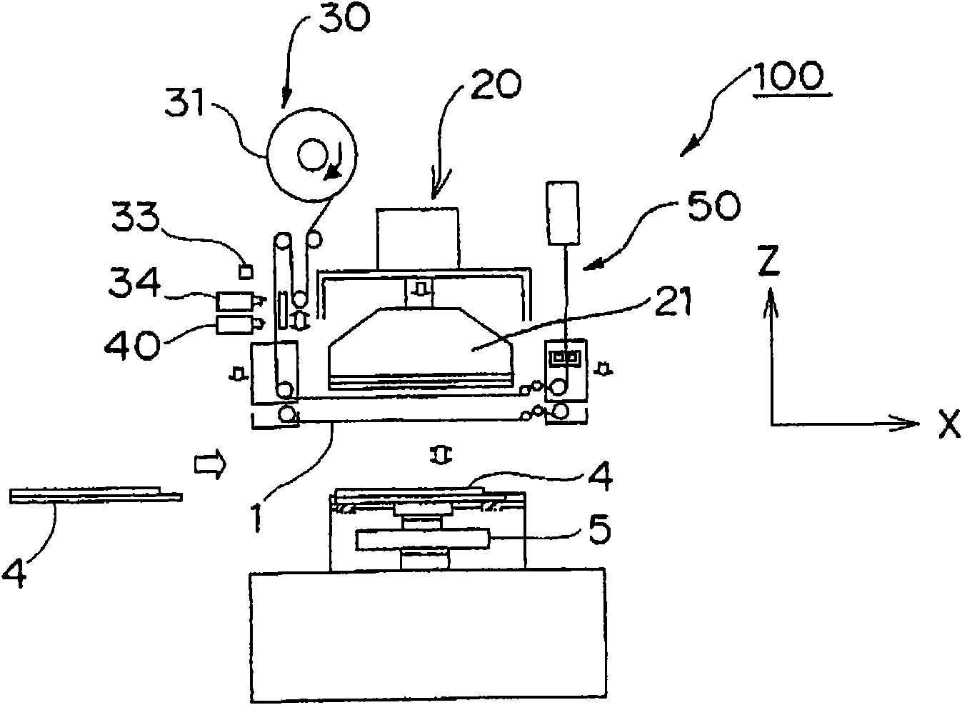
[0086] figure 1 It is a schematic perspective view which shows the structure of the ACF bonding apparatus 100 which is an example of the adhesive tape bonding apparatus with a release tape concerning 1st Embodiment of this invention. also, figure 2 A schematic plan view showing the ACF bonding apparatus 100, image 3 Indicates a schematic side view. Figure 1 ~ Figure 3The ACF bonding apparatus 100 shown is an ACF tape (tape member) that is bonded to one side of a parting tape using ACF (Anisotropic Conductive Film) as an example of an adhesive tape. ACF is bonded to a substrate (hereinafter referred to as "panel substrate"), and the ACF release tape is peeled off to form a device in a state where components can be mounted on a panel via the bonded ACF. Moreover, in the present embodiment, an ACF containing anisotropic conductive particles is used as an example of an adhesive tape for description, but it is also possible to use a tape that does not contain anisotropic con...
no. 2 Embodiment approach
[0114] In addition, the present invention is not limited to the above-described embodiments, and may be implemented in various other forms. E.g, Figure 14 The schematic diagram of : shows the apparatus structure for performing bonding process in the ACF bonding apparatus of 2nd Embodiment of this invention.
[0115] like Figure 14 As shown, in the ACF bonding apparatus of the second embodiment, although the bonding device 40 (for example, a wedge-shaped protruding tool 73 is attached) is provided as the same bonding device 40 as that of the first embodiment, other than that, in the bonding device 40 An ACF discarding device 80 is provided adjacent to the downstream side in the belt conveyance direction.
[0116] The ACF discarding device 80 is to use its adhesiveness to bond the ACF3 to be removed in the ACF tape 1, thereby peeling and removing it from the release tape 2, and performing the so-called "discarding ( て打ち) processing" device. Furthermore, the ACF discarding...
no. 3 Embodiment approach
[0125] Figure 16 It is a schematic diagram which shows the partial structure of the ACF bonding apparatus 110 which concerns on 3rd Embodiment of this invention. like Figure 16 As shown, the ACF bonding apparatus 110 of the third embodiment has a structure in which, in the bonding apparatus 120, the arrangement of the heating unit 122 and the table 121 is reversed with respect to the conveyance path of the ACF tape.
[0126] Specifically, as Figure 16 As shown, a table 121 is disposed between the cutter 34 and the ACF discarding device 80 . Furthermore, the heating unit 122 is arranged so as to face the table 121 across the conveyance path of the ACF tape. The heating unit 122 is arranged on the left side of the head 21 of the crimping head unit 20 in the drawing, and is movable so as to approach the table 121 during pressurization and heating operations for bonding processing. Furthermore, the heating unit 122 includes a protruding tool 123 and a heater 124 . In addit...
PUM
| Property | Measurement | Unit |
|---|---|---|
| width | aaaaa | aaaaa |
| thickness | aaaaa | aaaaa |
| width | aaaaa | aaaaa |
Abstract
Description
Claims
Application Information
 - R&D
- Intellectual Property
- Life Sciences
- Materials
- Tech Scout
- Unparalleled Data Quality
- Higher Quality Content
- 60% Fewer Hallucinations
Browse by: Latest US Patents, China's latest patents, Technical Efficacy Thesaurus, Application Domain, Technology Topic, Popular Technical Reports.
© 2025 PatSnap. All rights reserved.Legal|Privacy policy|Modern Slavery Act Transparency Statement|Sitemap|About US| Contact US: help@patsnap.com