Milling machine

A milling machine and shaft milling technology, applied in metal processing mechanical parts, driving devices, metal processing equipment, etc., can solve the problems of limited adjustment range, affecting output power, and equipment failures, etc., to achieve a large processing range and output power. Stable and Reliable Effects

Active Publication Date: 2015-06-10
东莞市鑫国丰机械有限公司
View PDF5 Cites 0 Cited by
  • Summary
  • Abstract
  • Description
  • Claims
  • Application Information

AI Technical Summary

Problems solved by technology

Due to the large number of structural parts required by the transmission system, the installation location also has high coordination requirements. Every time the speed is changed, the gears need to be separated and combined, and the equipment is prone to failure.
[0003] Existing machine tools use servo motors as the power source, and the speed adjustment of the servo motor can be used to adjust the final number of revolutions of the machining axis, but the change in the number of revolutions of the servo motor will affect its actual output power, so the adjustment range is limited

Method used


Image

  • Milling machine
  • Milling machine

Examples


no. 1 approach

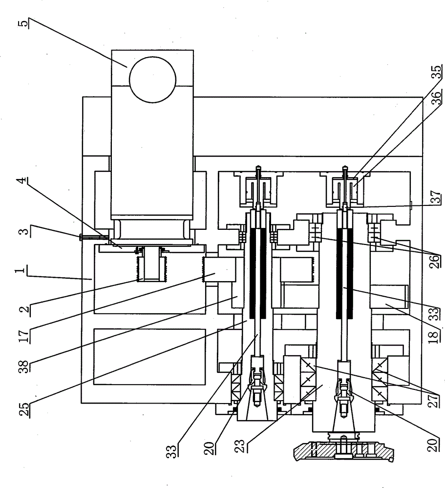
[0019] Such as figure 1 The shown milling machine comprises a spindle box 1, a servo motor 5, a first milling shaft 25, and a second milling shaft 23; A pre-tightening adjustment screw 3 is provided between the box 1 and the servo motor seat 4 for adjusting the position of the servo motor 5; the first milling shaft 25 is installed in the headstock 1 through a non-axial positioning bearing and a positioning bearing, The second milling shaft 23 is installed in the headstock 1 through a non-axial locating bearing and a locating bearing. In this embodiment, the non-axial locating bearing is a double row cylindrical roller bearing 26, and the axial locating bearing is an angular The contact bearing 27, the double row cylindrical roller bearing 26 is installed on the first milling shaft 25 and the second milling shaft 23 away from the end of the milling cutter, and the angular contact bearing 27 is installed on the first milling shaft 25 and the second milling shaft 23 close to the ...

no. 2 approach

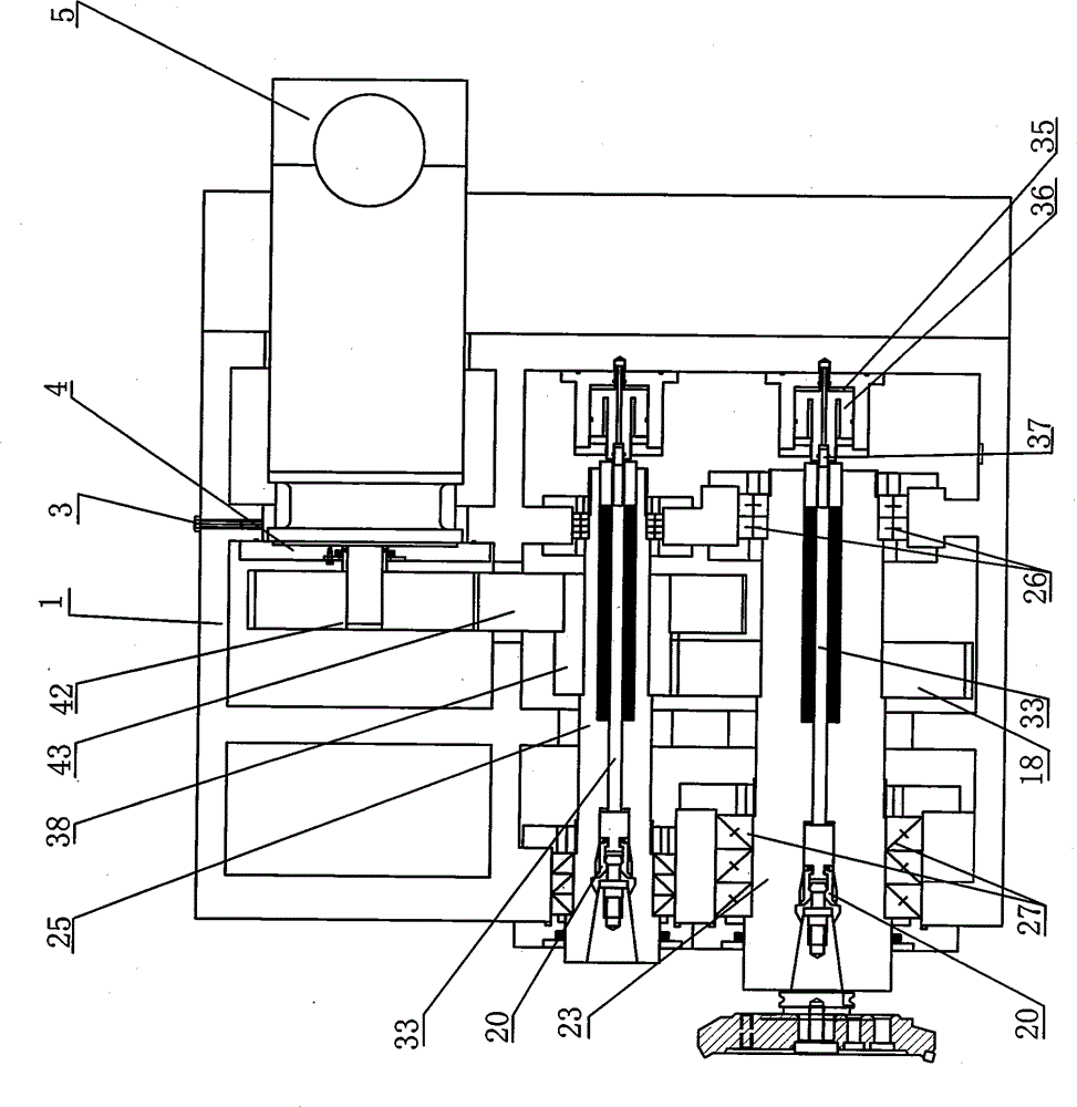
[0027] Such as figure 2 The shown milling machine comprises a spindle box 1, a servo motor 5, a first milling shaft 25, and a second milling shaft 23; A pre-tightening adjustment screw 3 is provided between the box 1 and the servo motor seat 4 for adjusting the position of the servo motor 5; the first milling shaft 25 is installed in the headstock 1 through a non-axial positioning bearing and a positioning bearing, The second milling shaft 23 is installed in the headstock 1 through a non-axial locating bearing and a locating bearing. In this embodiment, the non-axial locating bearing is a double row cylindrical roller bearing 26, and the axial locating bearing is an angular The contact bearing 27, the double row cylindrical roller bearing 26 is installed on the first milling shaft 25 and the second milling shaft 23 away from the end of the milling cutter, and the angular contact bearing 27 is installed on the first milling shaft 25 and the second milling shaft 23 close to the...


PUM


Abstract

The invention discloses a milling machine, comprising a spindle box, a first milling shaft, a second milling shaft and a servo motor. The power of the servo motor is transmitted to the first milling shaft and the second milling shaft by a main transmission system. The first milling shaft is a middle transmission shaft between the second milling shaft and the servo motor. The milling machine can lower the cost, simplify the transmission system, ensure low damage possibility of the transmission system, prolong the service life of the machine tool, simultaneously optimize the motor power and savethe energy.

Description

technical field [0001] The invention relates to a milling machine, in particular to a milling machine with two processing axes and a transmission system. Background technique [0002] Mechanical equipment occupies a dominant position in various processing, especially lathes, milling machines, boring machines, planers, grinding machines and other equipment. Now, in order to automate processing, improve processing speed and precision, CNC machine tools have appeared; among the above mechanical equipment, milling machines It is used to process flat parts, and flat processing is often encountered in mechanical processing. In the past milling process, the demand for cutting elements was limited by cutting conditions, such as different materials, different tools used, different tool sizes, different numbers of tools, different characteristics of roughing and finishing, and the cutting speed and spindle transmission The demand for the size of the torque is also different, which re...

Claims


Application Information

Patent Timeline
Patent Type & Authority Patents(China)
IPC IPC(8): B23Q5/10
Inventor 简东灿
Owner 东莞市鑫国丰机械有限公司
Why Eureka
Try Eureka