Slide-cylinder gas distribution suspending piston engine

A piston engine and sliding cylinder technology, applied to internal combustion piston engines, engine components, combustion engines, etc., can solve the problems affecting the intake and exhaust valve intake and exhaust areas, the reduction of two-stroke engine emission performance, intake and exhaust efficiency Low-level problems, to achieve the effect of improving life, environmental performance, and prolonging service life

Active Publication Date: 2010-03-03
张家港市乐余科创园投资发展有限公司
View PDF6 Cites 2 Cited by
  • Summary
  • Abstract
  • Description
  • Claims
  • Application Information

AI Technical Summary

Problems solved by technology

Although this has played a lubricating effect, in the structure where the air passage of the two-stroke engine is arranged on the side wall of the cylinder, the machine oil will enter the combustion chamber with the air flow, and the combustion of the machine oil in the combustion chamber is insufficient. Reduce the emission performance of the two-stroke engine, produce excessive harmful emissions, pollute the environment, or the engine oil will directly enter the exhaust passage, and be discharged into the atmosphere with the engine exhaust gas, causing more serious environmental pollution
In a traditional four-stroke engine, since the intake and exhaust valves are all set on the cylinder head, no matter whether the multi-valve technology or the traditional single-valve technology is adopted, the size of the intake and exhaust valves is limited by the cross-sectional area of ​​the cylinder. Affect the intake and exhaust area of ​​the intake and exhaust valves, making the intake and exhaust efficiency low

Method used


Image

  • Slide-cylinder gas distribution suspending piston engine
  • Slide-cylinder gas distribution suspending piston engine
  • Slide-cylinder gas distribution suspending piston engine

Examples


Embodiment Construction

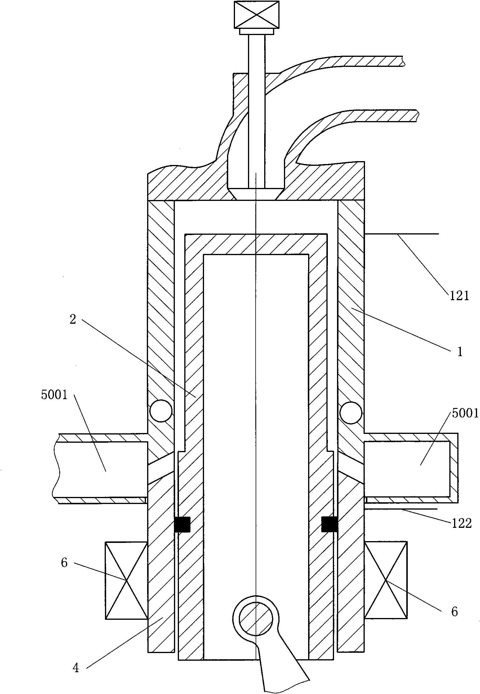
[0043] Such as figure 1 The shown sliding cylinder gas suspension piston engine includes a cylinder 1, a piston 2 and a sliding cylinder 4, and the piston 2 is all or partly arranged in the cylinder 1 at the position corresponding to the top dead center of the piston 2. The piston 2 and the piston 2 are connected within the entire stroke range or part of the stroke range between the top dead center 121 on the cylinder 1 and the bottom dead center 122 on the cylinder 1 corresponding to the piston bottom dead center of the piston 2. The cylinder 1 is suspended or quasi-suspended, the piston 2 is in sealing and sliding contact with the sliding cylinder 4, and the sliding cylinder 4 is in sealing contact with or separated from the cylinder 1 under the control of the sliding cylinder timing control mechanism 6. A side wall air distribution channel 5001 is provided at the interface where the cylinder 1 cooperates with the sliding cylinder 4 .

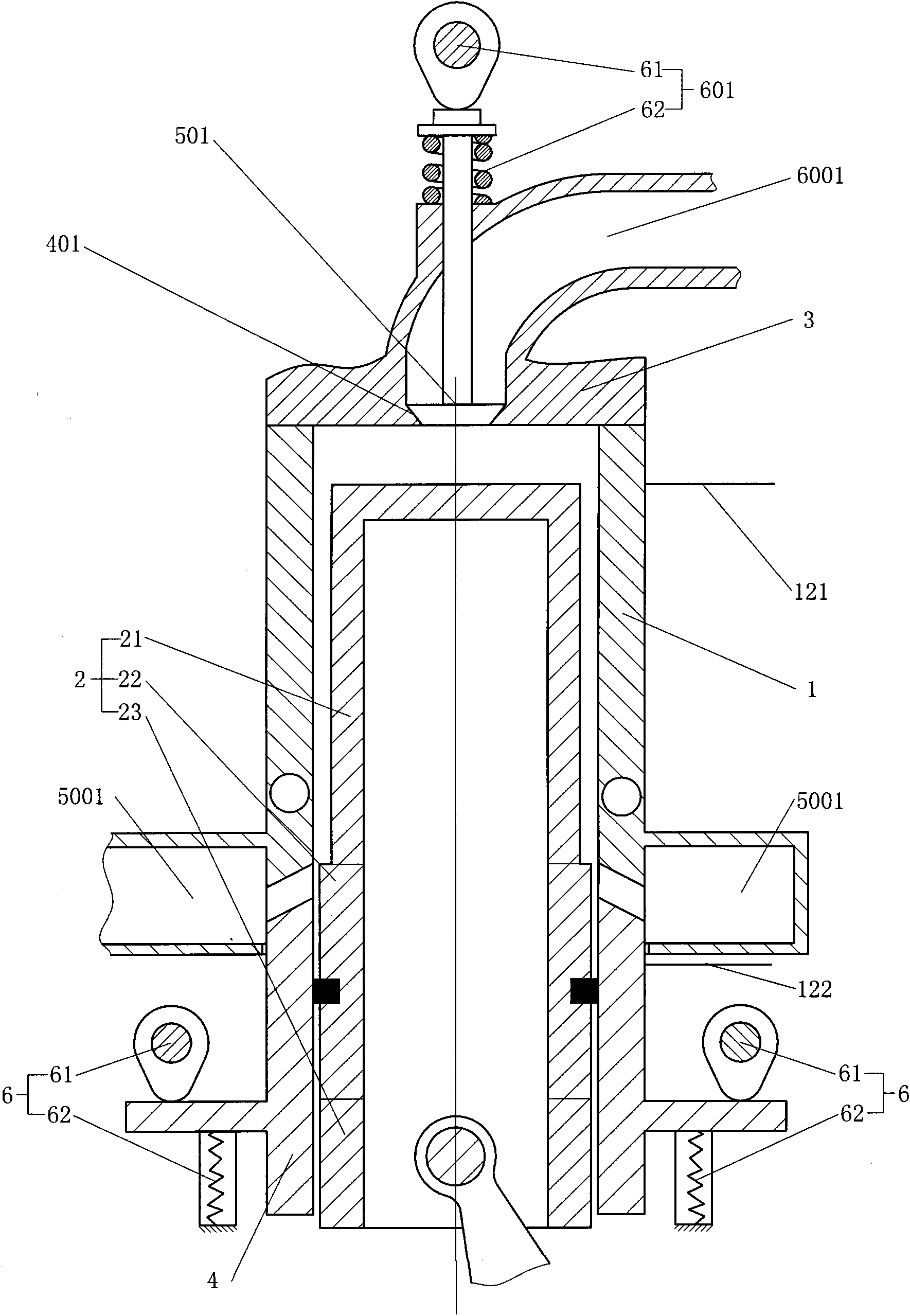
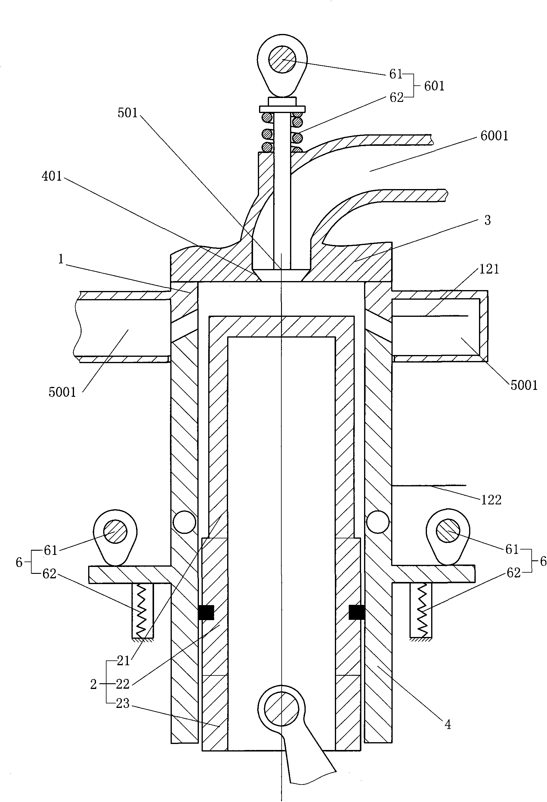
[0044] Such as figure 2 In the slid...


PUM


Abstract

The invention discloses a slide-cylinder gas distribution suspending piston engine which comprises a cylinder, pistons and a slide cylinder, wherein the pistons are completely or partly arranged inside the cylinder; the pistons and the cylinder is arranged in a suspending way or exactly suspending way in the whole or part stroke range between a top dead center which is arranged on the cylinder andcorresponding to a top dead center of the piston and a bottom dead center that is arranged on the cylinder and corresponding to a bottom dead center of the piston; the pistons are contacted with theslide cylinder in a sealing and sliding way; the slide cylinder is controlled to be contacted with the cylinder in a sealing way or separated from the cylinder by a slide cylinder timing control mechanism; and a side wall gas distribution channel is arranged at the interface where the cylinder is matched with the slide cylinder. As the position of a gas valve seat hole arranged at the side of thecylinder is on a sealing section of the pistons, engine oil can be avoided being blown into an air channel, the engine oil which is blown into the air channel is prevented from entering a combustion chamber or being directly discharged into the atmosphere, the environmental pollution can be reduced, and the service life of the engine is prolonged.

Description

technical field [0001] The invention relates to the field of engines. Background technique [0002] In a traditional two-stroke engine, the piston is in a sliding and sealed connection with the inner wall of the cylinder. In order to maintain the relative movement between the piston and the cylinder, it is necessary to use oil to lubricate the piston and cylinder. Although this has played a lubricating effect, in the structure where the air passage of the two-stroke engine is arranged on the side wall of the cylinder, the machine oil will enter the combustion chamber with the air flow, and the combustion of the machine oil in the combustion chamber is insufficient. The emission performance of the two-stroke engine is reduced, excessive harmful emissions are produced, and the environment is polluted, or the engine oil will directly enter the exhaust passage and be discharged into the atmosphere with the exhaust gas of the engine, causing more serious environmental pollution. ...

Claims


Application Information

Patent Timeline
Patent Type & Authority Applications(China)
IPC IPC(8): F02B75/40F01L1/34F02F3/00F02F1/00F02F1/42F02B37/00
CPCY02T10/144Y02T10/12
Inventor 靳北彪
Owner 张家港市乐余科创园投资发展有限公司
Why Eureka
Try Eureka