

Far-infrared heat energy wood floor and manufacturing method and paving method thereof
A far-infrared, manufacturing method technology, applied in the field of wood flooring, can solve the problems of failure to overcome wood defects, failure to solve the problems of heating wood floor manufacturing technology and production process, etc., and achieve the effect of ingenious design
- Summary
- Abstract
- Description
- Claims
- Application Information
AI Technical Summary
Problems solved by technology
Method used
Image

Examples
Embodiment Construction
[0078] In order to understand the technical content of the present invention more clearly, the following examples are given in detail.
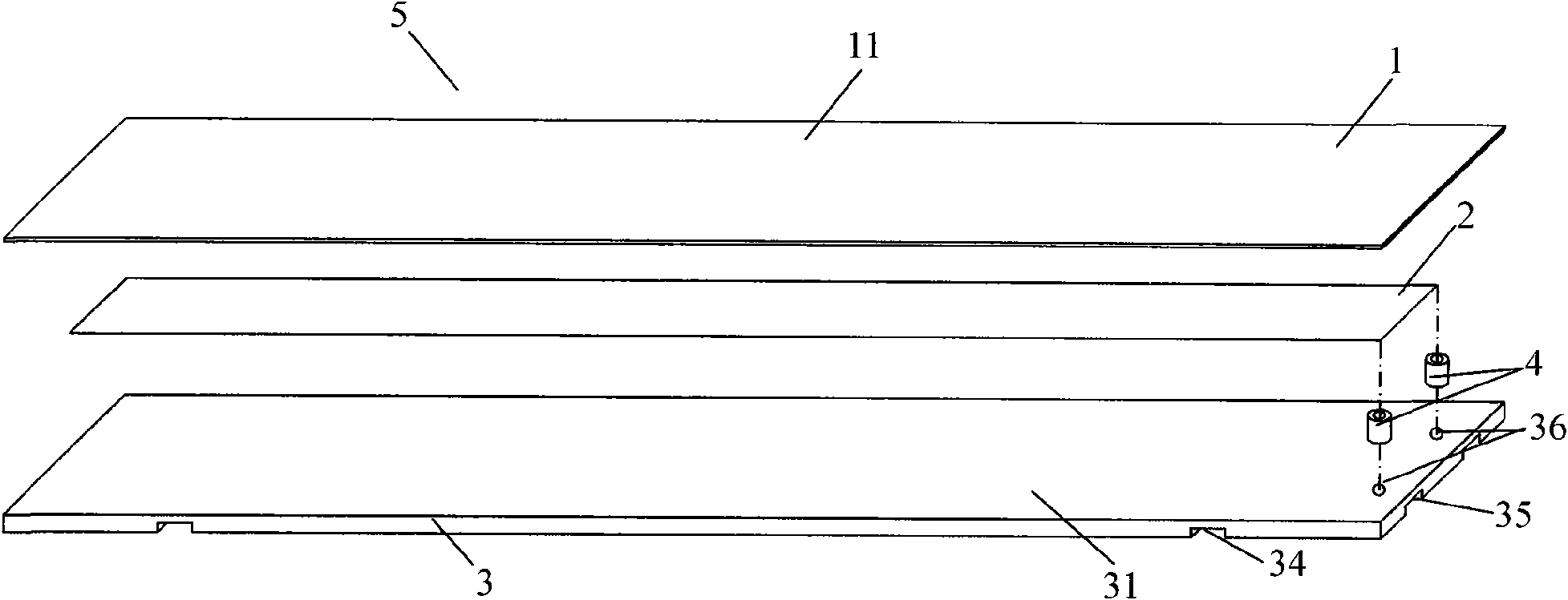
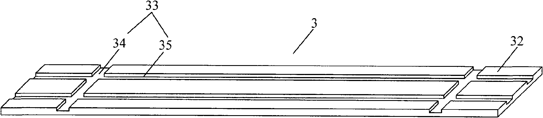
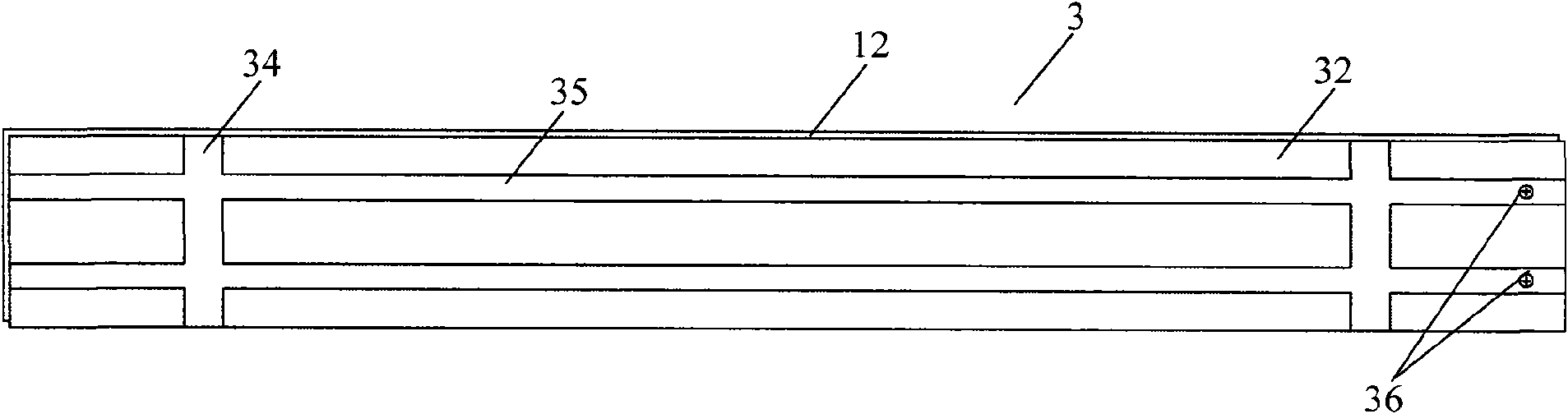
[0079] see Figure 1~5 As shown, the far-infrared heat energy wooden floor 5 of the present invention comprises a wooden floor surface board 1, a carbon crystal electric heating material sheet 2 and a wooden floor substrate 3, and the wooden floor surface board 1 includes a first surface 11 and a 11 opposite to the second surface (not shown), the wood floor substrate 3 includes a third surface 31 and a fourth surface 32 opposite to the third surface 31, and the carbon crystal electrothermal material sheet 2 is located on the wood The floor surface board 1 and the wooden floor substrate 3 are respectively attached to the second surface and the third surface 31 .
[0080] In a specific embodiment of the present invention, the wood floor surface board 1 has an air-dry density of 0.5-0.7 g / cm 3 The hardwood board, the thickness of the wooden fl...
PUM
| Property | Measurement | Unit |
|---|---|---|
| Air dry density | aaaaa | aaaaa |
| Thickness | aaaaa | aaaaa |
| Thickness | aaaaa | aaaaa |
Abstract
Description
Claims
Application Information