
Two-rotor axial magnetic flux switching type mixed excitation synchronous generator

A hybrid excitation synchronous and axial flux technology, applied in the direction of synchronous machine components, electrical components, electromechanical devices, etc., can solve the problems of increased magnetic saturation, reduced utilization of permanent magnets, increased iron loss and magnetic flux leakage, etc., to achieve Effects of shortened length, reduced heat loss, and reduced resistance and excitation loss

Inactive Publication Date: 2010-03-03
JIANGXI UNIV OF SCI & TECH
View PDF4 Cites 40 Cited by
  • Summary
  • Abstract
  • Description
  • Claims
  • Application Information

AI Technical Summary

Problems solved by technology

There are two problems in this motor: (1) The permanent magnet flux passes through the stator core at the end of the excitation coil to form a loop, which reduces the utilization rate of the permanent magnet; (2) With the increase of the excitation current, when the electric excitation magnetic field line and the permanent magnet When the magnetization directions of the magnets are consistent, the magnetic saturation in the stator core at the end of the excitation coil increases, and the iron loss and magnetic flux leakage increase accordingly

Method used


Image

  • Two-rotor axial magnetic flux switching type mixed excitation synchronous generator
  • Two-rotor axial magnetic flux switching type mixed excitation synchronous generator
  • Two-rotor axial magnetic flux switching type mixed excitation synchronous generator

Examples


Embodiment Construction

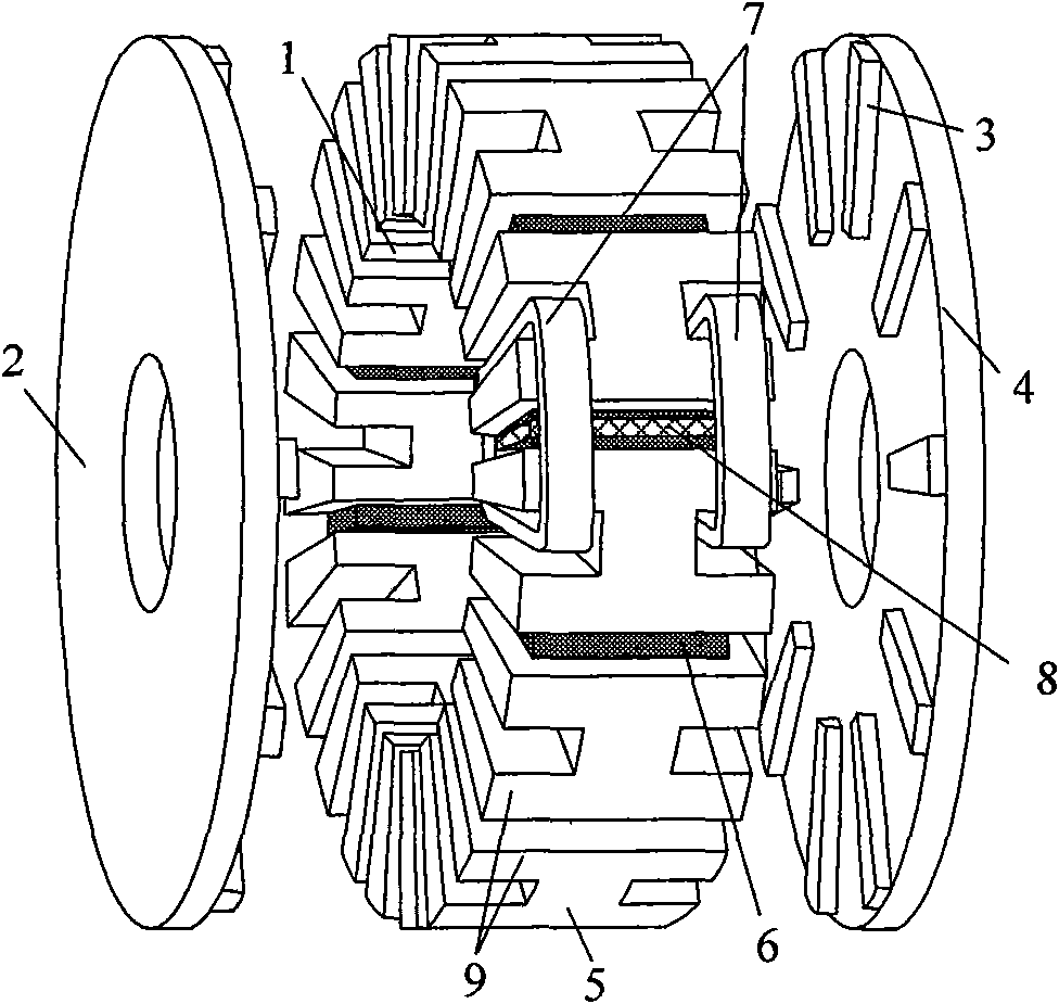
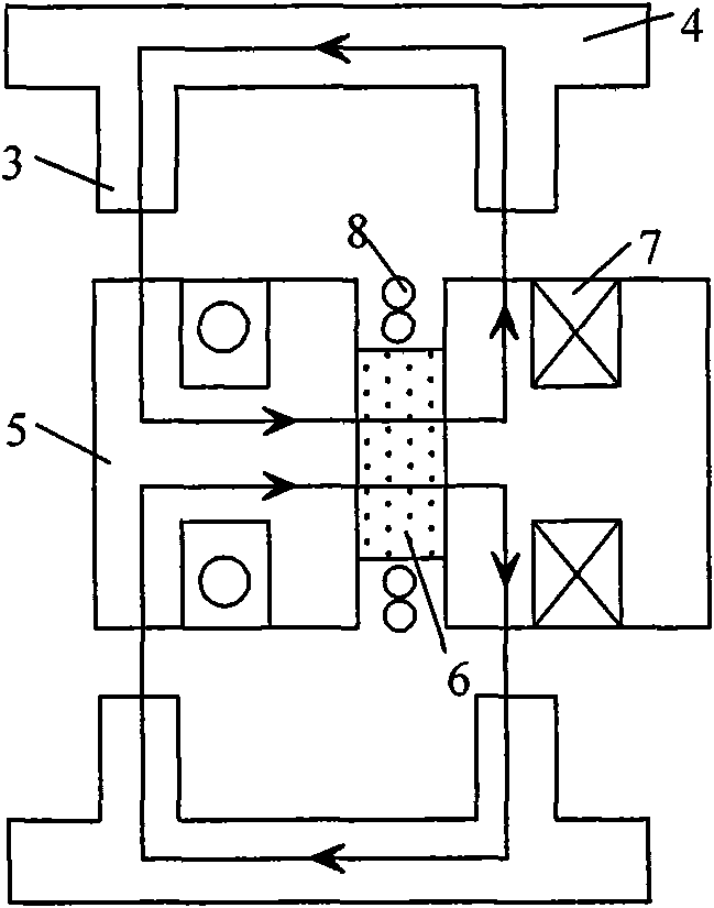
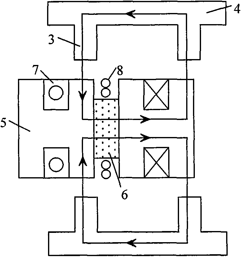
[0022] The stator of the present invention is different from the stator of an ordinary AC motor. The stator is assembled into a circle by the "H" type unit stator core and fixed on the motor casing. The armature winding 7 is scattered in the stator teeth of the adjacent "H" type unit stator core. superior, figure 1 Only the distribution of a concentrated winding on the motor stator is given in the figure, and the rest of the windings are not drawn. The permanent magnets are staggeredly inlaid in the space formed by the stator cores of adjacent units, magnetized tangentially, and the field windings are axially wound on the surface of the permanent magnets, with high space utilization and compact structure; in addition, the ends of the field windings are short, The excitation loss of the motor is small, and the efficiency of the motor is improved.

[0023] The stator adopts a structure composed of "H" type unit stator core, and the rotor adopts a disc structure, which can great...


PUM


Abstract

The invention relates to the generator technology and in particular to a two-rotor axial magnetic flux switching type mixed excitation synchronous generator which has high efficiency, direct driving and variable speed and constant frequency; the generator comprises a stator and rotors; the stator is assembled to be round by 6a H-shaped unit stator cores, a is positive integer, an armature windingadopts a concentrated winding which is circumferentially wound on a stator tooth adjacent to the H-shaped unit stator core, permanent magnets are arrayed between the adjacent H-shaped unit stator cores in a staggering way, the permanent magnet charges the magnetism tangentially, an exciting winding is axially wound on the surface of the permanent magnet, so as to generate circumferential magneticfield by direct current in the exciting winding and enhance or weaken the permanent magnet field; the rotor comprises a rotor magnet yoke and a rotor pole fixed at the inner side of the rotor magnet yoke, the rotor and the stator are arranged axially. The invention is a novel mixed excitation synchronous generator which has high efficiency, direct driving and wide voltage regulating range.

Description

technical field [0001] The invention relates to generator technology, in particular to a high-efficiency, direct-drive, variable-speed and constant-frequency dual-rotor axial flux switching hybrid excitation synchronous generator. Background technique [0002] There is no winding on the rotor of the permanent magnet motor, and the structure is simple, so the motor has no excitation loss, and has high efficiency and reliable operation; the rare earth permanent magnet material has high coercive force and high remanence density, so the rare earth permanent magnet motor also has high power density and good performance etc.; however, the inability to adjust the magnetic field has become a bottleneck for the application of such motors as generators and motors. [0003] Hybrid excitation motor is a kind of flux controllable permanent magnet synchronous motor. Due to the existence of auxiliary excitation winding, hybrid excitation motor can not only inherit many advantages of perman...

Claims


Application Information

Patent Timeline
IPC IPC(8): H02K16/02H02K21/04H02K1/17
Inventor 刘细平任志斌杨杰
Owner JIANGXI UNIV OF SCI & TECH
Learn More