

Control method for alternating current solid-state power switch
A solid-state power switch, solid-state switch technology, applied in electronic switches, electrical components, pulse technology, etc., can solve the problems of many triggering times, large voltage drop of thyristor on-state, high power consumption, etc. The effect of low power consumption
- Summary
- Abstract
- Description
- Claims
- Application Information
AI Technical Summary
Problems solved by technology
Method used
Image

Examples
specific Embodiment
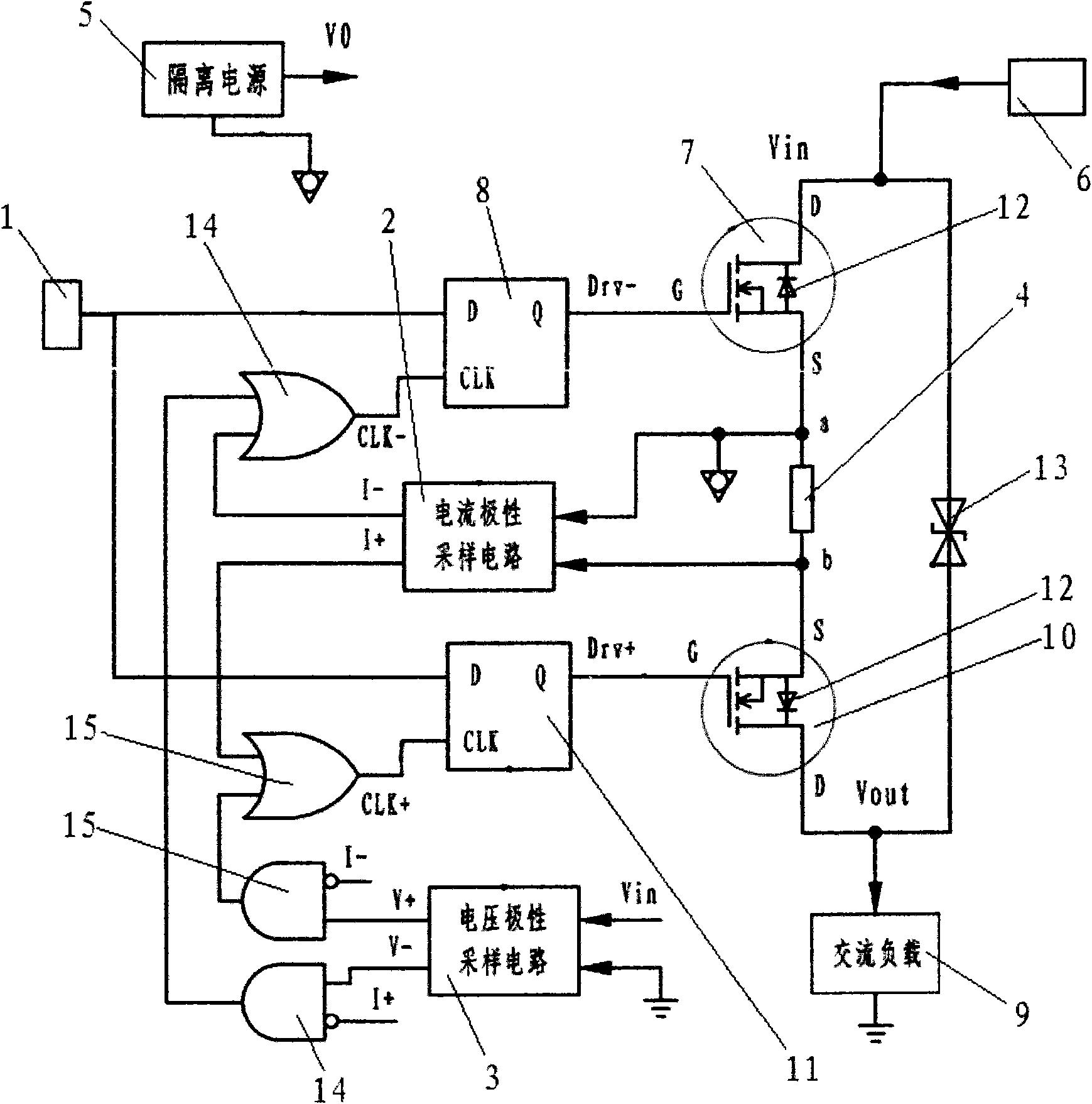
[0033] The specific embodiment design circuit is as follows:
[0034] Set the control signal input terminal for inputting the on / off control signal; set the isolated power supply;
[0035]A positive control switch and a negative control switch are set, the isolated power supply ground is connected to the source of the negative control switch, the AC power supply is connected to the drain of the negative control switch, and the drain of the positive control switch is grounded through the AC load;
[0036] A bidirectional voltage transient controller, a current sampling resistor and a load current polarity sampling circuit module are arranged between the positive control switch and the negative control switch. The drain of the switch is connected, the two ends of the current sampling resistor are respectively connected with the source of the positive control switch and the source of the negative control switch, and the load current polarity sampling circuit module is connected w...
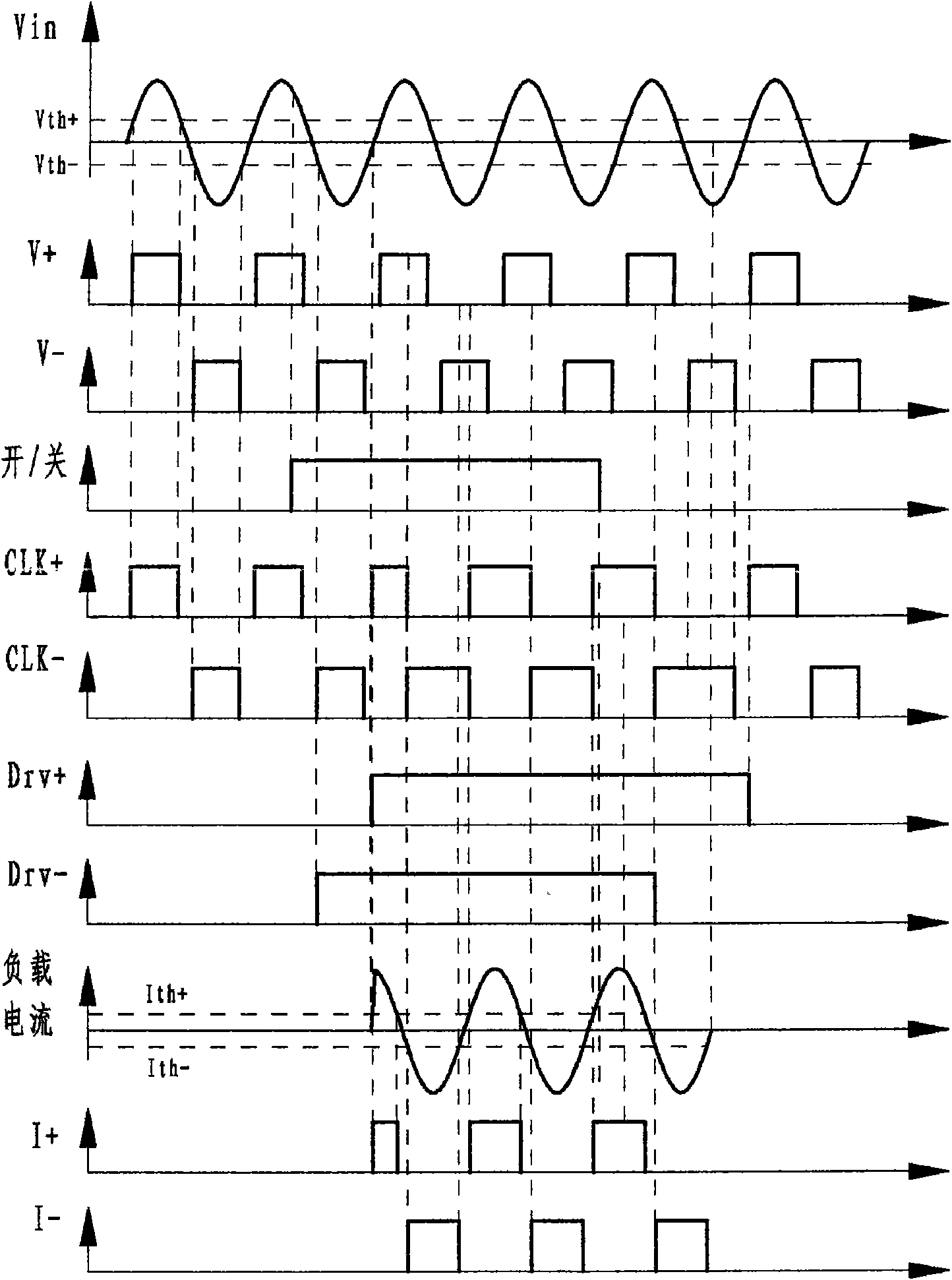
Embodiment 2
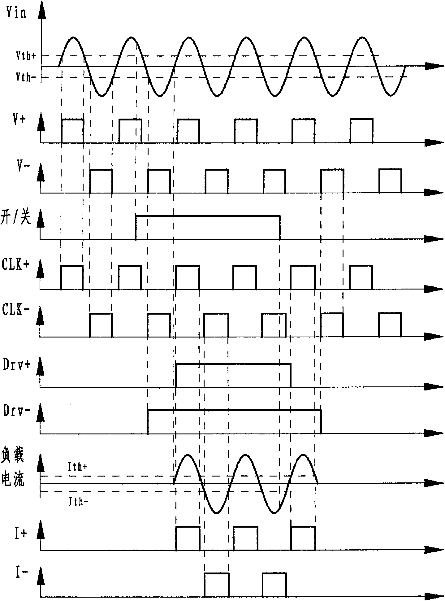
[0038] Set the line voltage polarity sampling circuit module and the load current polarity sampling circuit module, the line voltage polarity sampling circuit module is connected to the AC power supply, and the line voltage polarity sampling circuit detects the AC between the input terminal Vin of the AC power supply and the ground of the AC power supply Voltage polarity (as attached figure 1 Embodiment 1), or detect the polarity of the AC voltage between the input terminal Vin of the AC power supply and the output Vout of the AC power (as attached Figure 5 Embodiment 2);
[0039] The first logic gate circuit 14 is set, the input terminal of the first logic gate circuit is connected with the load current polarity sampling circuit module, the input terminal of the first logic gate circuit is connected with the line voltage polarity sampling circuit module, and the first logic gate circuit The output end of the circuit is connected with the clock signal interface of the positi...
Embodiment 1
[0041] Embodiment 1 is a control method for an AC solid-state power switch with two logic gate circuits each having a multiplier and an adder. Embodiment 2 is a control method of an AC solid-state power switch with two logic gate circuits each having an adder.
[0042] figure 1 It is a control principle block diagram of Embodiment 1 of the present invention.
[0043] The source of the positive control switch and the source of the negative control switch are respectively connected to the load current polarity sampling circuit module, and the load current polarity sampling circuit module is respectively connected to the input terminals of two logic gate circuits, and the two logic gate circuits The output terminal of the positive control D-type flip-flop is connected with the clock signal interface of the negative-control D-type flip-flop, the AC power supply is connected with the line voltage polarity sampling circuit module, and the line voltage polarity sampling circuit modu...
PUM
 Abstract
Description
Claims
Application Information