
Reduction mechanism

A deceleration mechanism and speed technology, applied in the direction of mechanical equipment, transmission parts, gear transmission, etc., can solve the problems of complexity, low efficiency, high overall height, etc., and achieve the effect of simple and compact structure and compact overall structure

Inactive Publication Date: 2010-03-03
MCI荷兰公司
View PDF0 Cites 1 Cited by
  • Summary
  • Abstract
  • Description
  • Claims
  • Application Information

AI Technical Summary

Problems solved by technology

[0007] The disadvantage of a harmonic drive reduction mechanism is that it is relatively complex due to the many parts involved
In addition, the overall height of the mechanism is relatively high and the efficiency is relatively low

Method used


Image

  • Reduction mechanism
  • Reduction mechanism
  • Reduction mechanism

Examples


Embodiment Construction

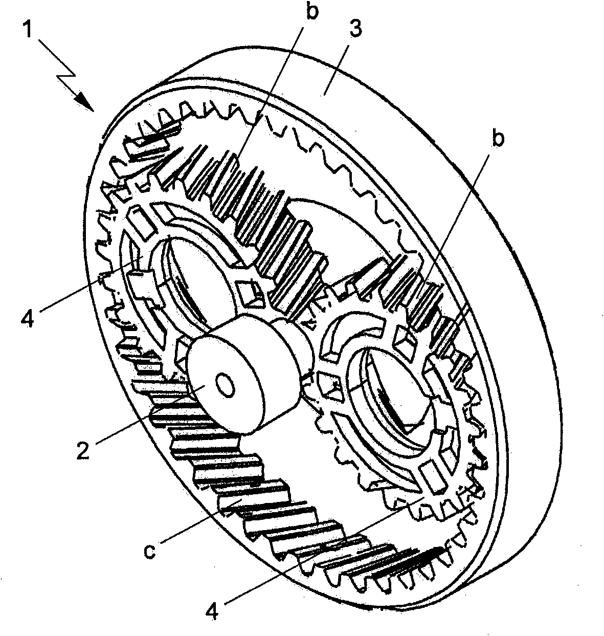
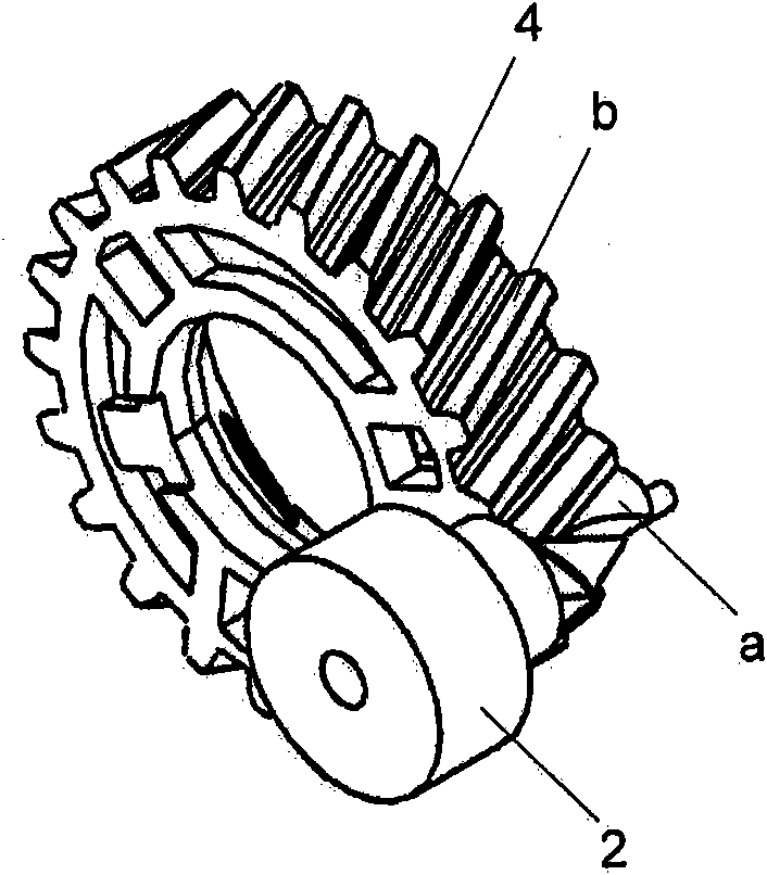
[0031] figure 1 A reduction mechanism according to the invention is shown. The reduction mechanism 1 includes an input gear 2 provided with involute external teeth a. The input gear 2 is provided with involute external teeth b, such as figure 2 shown. exist figure 2 In the exemplary embodiment, the input gear 2 is designed with two teeth.

[0032] In addition, the reduction mechanism 1 further includes an output gear 3 provided with involute internal teeth c. In use, the speed of the output gear 3 is lower than the speed of the input gear 2 . The speed is reduced according to the transmission ratio of the reduction mechanism.

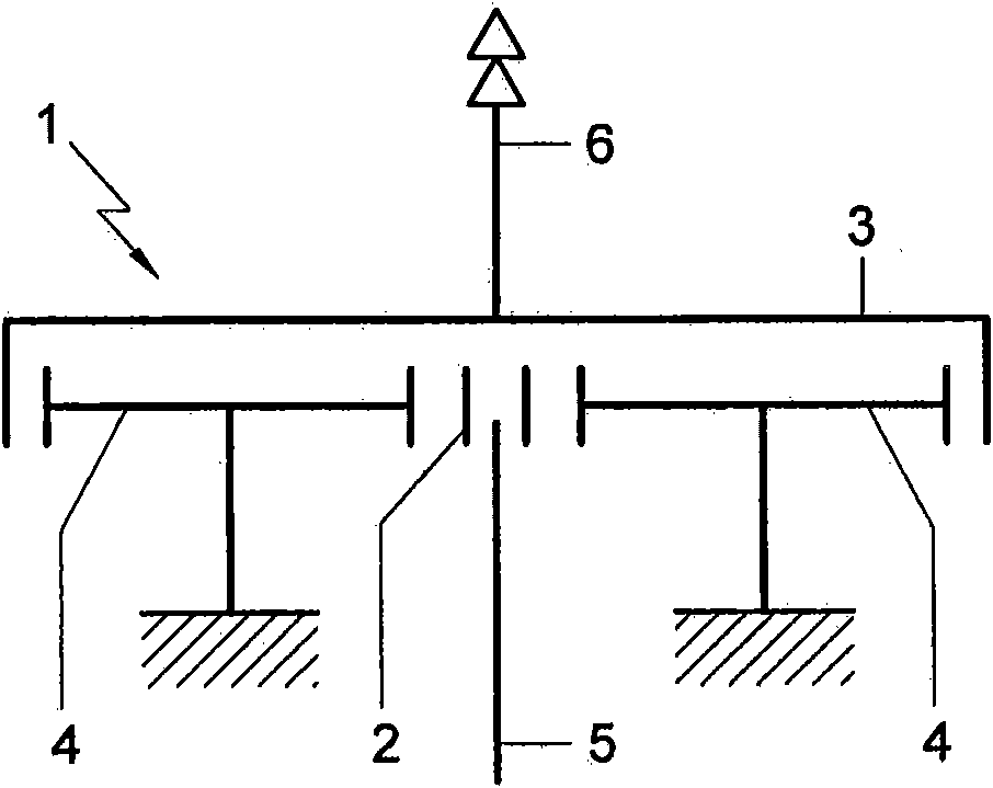
[0033] in addition, figure 1 The reduction mechanism 1 in the exemplary embodiment also includes two intermediate gears 4 arranged symmetrically with respect to the input gear 2 . Each intermediate gear 4 is provided with external teeth b and cooperates with both the input gear 2 and the output gear 3 .

[0034] The input gear 2 is located in...


PUM


Abstract

A reduction mechanism, comprising - an input gear wheel (2) provided with an outer toothing, for coupling with a driving motor, which input gear wheel is provided with an evoloid toothing with only 1or 2 teeth; - an output gear wheel (3) provided with an inner toothing, whose speed during use is lower than the speed of the input gear wheel; - at least one intermediate gear wheel (4) operative between the input gear wheel and the output gear wheel and whose rotation axis is fixedly arranged.

Description

technical field [0001] The invention relates to a reduction mechanism. Background technique [0002] Reduction mechanisms are well known and are used to shift the speed of an electric machine, such as an electric motor, to a low speed. [0003] A known reduction mechanism is a planetary gear transmission. A planetary gear transmission generally comprises an input gear provided with external teeth, which cooperates with at least one planet gear. The rotation shafts of the planetary gears move around the input gear and are not fixedly arranged. The planetary gears cooperate with the ring output gear. [0004] When a high transmission ratio is desired in a particular application, a reduction mechanism based on the principle of "harmonic drive", for example, is utilized. [0005] The harmonic drive reduction mechanism includes an outer ring gear with internal teeth, in which an inner ring gear with external teeth can run, which is flexible but connected to a fixed base (fixe...

Claims


Application Information

Patent Timeline
IPC IPC(8): F16H1/22F16H57/08
CPCF16H1/227F16H55/0806F16H2055/0893F16H1/22F16H57/08
Inventor 斯特凡·弗里茨·布劳沃尔
Owner MCI荷兰公司
Learn More