Membrane isolating type oil tank

A membrane isolation and oil tank technology, applied in the direction of containers, packaging, transportation and packaging, etc., can solve the problems of respiratory loss, environmental protection, safety, quality, etc., and achieve the effects of protecting the environment, ensuring safety, and eliminating oil and gas

Inactive Publication Date: 2010-03-10
李束为
View PDF0 Cites 16 Cited by
  • Summary
  • Abstract
  • Description
  • Claims
  • Application Information

AI Technical Summary

Problems solved by technology

[0005] In order to overcome the respiratory loss during the storage and transportation of oil products in the existing oil tanks and the resulting problems of environmental protection, safety, and quality, the technical solution of the present invention is to provide a membrane-isolated oil tank to effectively isolate oil products The contact with air reduces or even eliminates the generation of oil and gas, thereby protecting the environment, ensuring the safety of oil storage and transportation, and ensuring the quality of oil products

Method used


Image

  • Membrane isolating type oil tank
  • Membrane isolating type oil tank
  • Membrane isolating type oil tank

Examples


Embodiment approach 1

[0036] Implementation Mode 1: Top-loaded air bag type oil tank

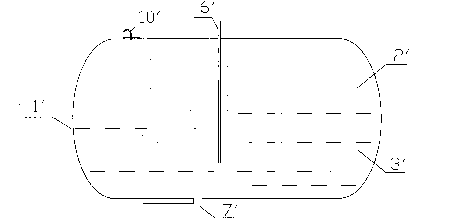
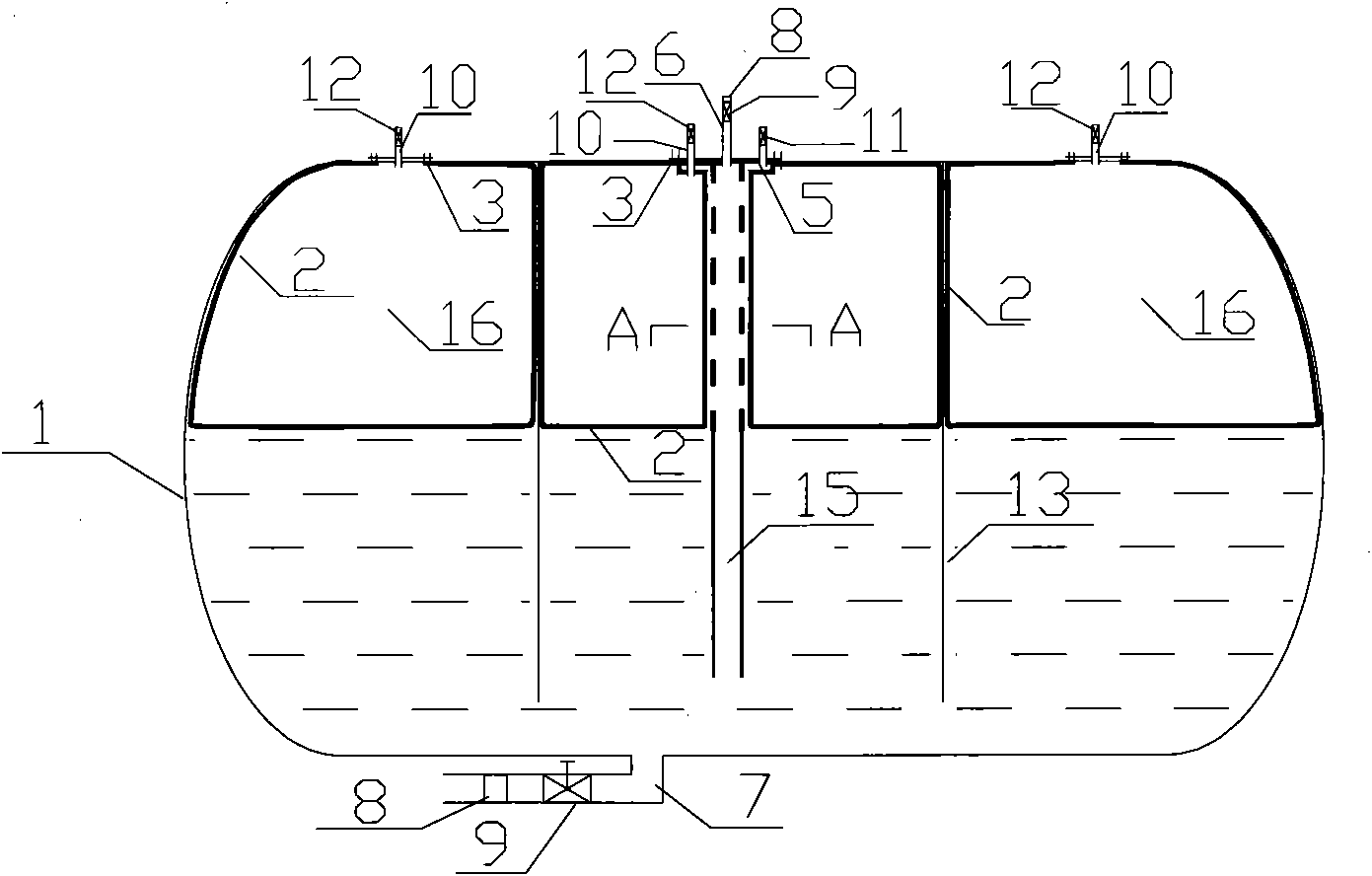
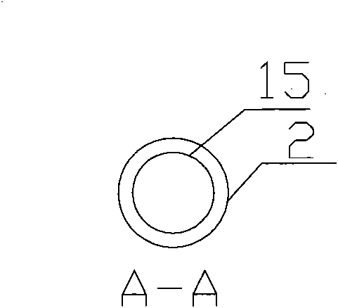
[0037] Such as Figure 2a As shown, it is a structural schematic diagram of a top-loaded air bag type oil tank according to an embodiment of the present invention. The membrane-isolated oil tank includes a tank body 1, an oil inlet pipe 6, an oil outlet pipe 7 and a breathing pipe 10 located on the tank body 1, and at least one wave-proof partition 13 perpendicular to the oil surface is provided in the tank body 1 , Both sides of the wave-proof bulkhead 13 are provided with an air bag 16 formed by the membrane 2 for isolating oil and air. In this embodiment, there are three airbags 16 separated by two anti-wave baffles 13, and the anti-wave baffles 13 have a certain distance from the bottom of the tank body 1 to facilitate oil circulation. The anti-wave partition 13 is connected with the top and both sides of the tank body 1, and is not completely sealed, leaving a certain gap, which is beneficial to the circul...

Embodiment approach 2

[0046] Embodiment 2: Bottom-loaded oil-pneumatic bag type oil tank

[0047] Such as image 3 As shown in FIG. 2 , it is a structural schematic diagram of the second embodiment of the present invention. The oil inlet pipe 6 is located at the bottom of the tank body 1 and can share a pipeline with the oil outlet pipe 7 . Other features of the second embodiment are the same as those of the first embodiment, and will not be repeated here.

Embodiment approach 3

[0048] Embodiment 3: Top-loaded oil bladder type oil tank

[0049] Such as Figure 4 , is a structural schematic diagram of the top-loaded oil bag type oil tank according to the third embodiment of the present invention. The membrane-isolated oil tank includes a tank body 1, an oil inlet pipe 6, an oil outlet pipe 7 and a breathing pipe 10 located on the tank body 1, and at least one wave-proof partition 13 perpendicular to the oil surface is provided in the tank body 1 , Both sides of the wave-proof baffle 13 are provided with oil pockets 17 formed by the membrane 2 for isolating oil and air. In this embodiment, there is an oil bag 17, and the anti-wave partition 13 has a certain distance from the bottom of the tank body 1 to facilitate the passage of the oil bag 17 and oil. The anti-wave partition 13 is connected with the top and both sides of the tank body 1, and is not completely sealed, leaving a certain gap, which is beneficial to the circulation of gas.

[0050] A pa...


PUM


Abstract

The invention discloses a membrane isolating type oil tank which comprises a tank body, an oil inlet pipe, an oil outlet pipe and a breathing pipe, wherein the oil inlet pipe, the oil outlet pipe, andthe breathing pipe are arranged on the tank body; and is characterized in that the tank body is internally provided with at least one anti-wave clapboard vertical to an oil surface, and two sides ofthe anti-wave clapboard are both provided with a bag formed by membrane and used for isolating oil from air. As the bag formed by the membrane isolates the air from the oil, the formation of oil gas is stopped, and when respiration is generated in the tank body, both exhalation air and breathed air are clean. Therefore, the contact between oil product and the air is effectively blocked, and the generation of oil gas is reduced or even eliminated, thus protecting the environment, guaranteeing the safety of the oil product during storage and transportation, and ensuring the quality of the oil product.

Description

technical field [0001] The invention relates to the field of storage and transportation of oil products, in particular to a membrane-isolated oil tank that adopts membrane separation storage and transportation technology to solve problems such as energy saving, environmental protection, safety, and quality in the process of oil storage and use. Background technique [0002] At present, oil products with higher volatility (such as gasoline, solvent oil, naphtha, aviation kerosene, light diesel oil and crude oil, etc.) There is size respiration, which leads to oil evaporation loss, and the oil evaporates and mixes with air to produce oil gas. Such as figure 1 Shown is a schematic diagram of the principle of oil and gas generation in an oil tank in the prior art. The tank body 1' is used for storing and transporting the oil product 3', and the oil product 3' enters the tank body 1' from the oil inlet pipe 6' and is discharged from the oil outlet pipe 7'. When the oil is load...

Claims


Application Information

Patent Timeline
Patent Type & Authority Applications(China)
IPC IPC(8): B65D88/02B65D90/38B65D90/32B65D90/00B65D90/52
Inventor 李束为
Owner 李束为
Why Eureka
Try Eureka