Process for forming a ferroelectric film, ferroelectric film, ferroelectric device, and liquid discharge apparatus

A ferroelectric, film-forming technology, applied in the manufacture/assembly of piezoelectric/electrostrictive devices, material selection for piezoelectric devices or electrostrictive devices, piezoelectric/electrostrictive/magnetostrictive devices and other directions, it can solve the problems of poor ferroelectricity, impractical technology, Pb, etc., and achieve the effect of improving ferroelectricity, suppressing the decrease of ferroelectricity, and good ferroelectricity

Inactive Publication Date: 2010-03-10
FUJIFILM CORP
View PDF1 Cites 0 Cited by
  • Summary
  • Abstract
  • Description
  • Claims
  • Application Information

AI Technical Summary

Problems solved by technology

However, techniques for lamination of repeated films are not practical
Also, with sol-gel technology, Pb deficiency is prone to occur
In the case of Pb deficiency, there is a tendency for ferroelectricity to deteriorate

Method used


Image

  • Process for forming a ferroelectric film, ferroelectric film, ferroelectric device, and liquid discharge apparatus
  • Process for forming a ferroelectric film, ferroelectric film, ferroelectric device, and liquid discharge apparatus
  • Process for forming a ferroelectric film, ferroelectric film, ferroelectric device, and liquid discharge apparatus

Examples


Embodiment 1

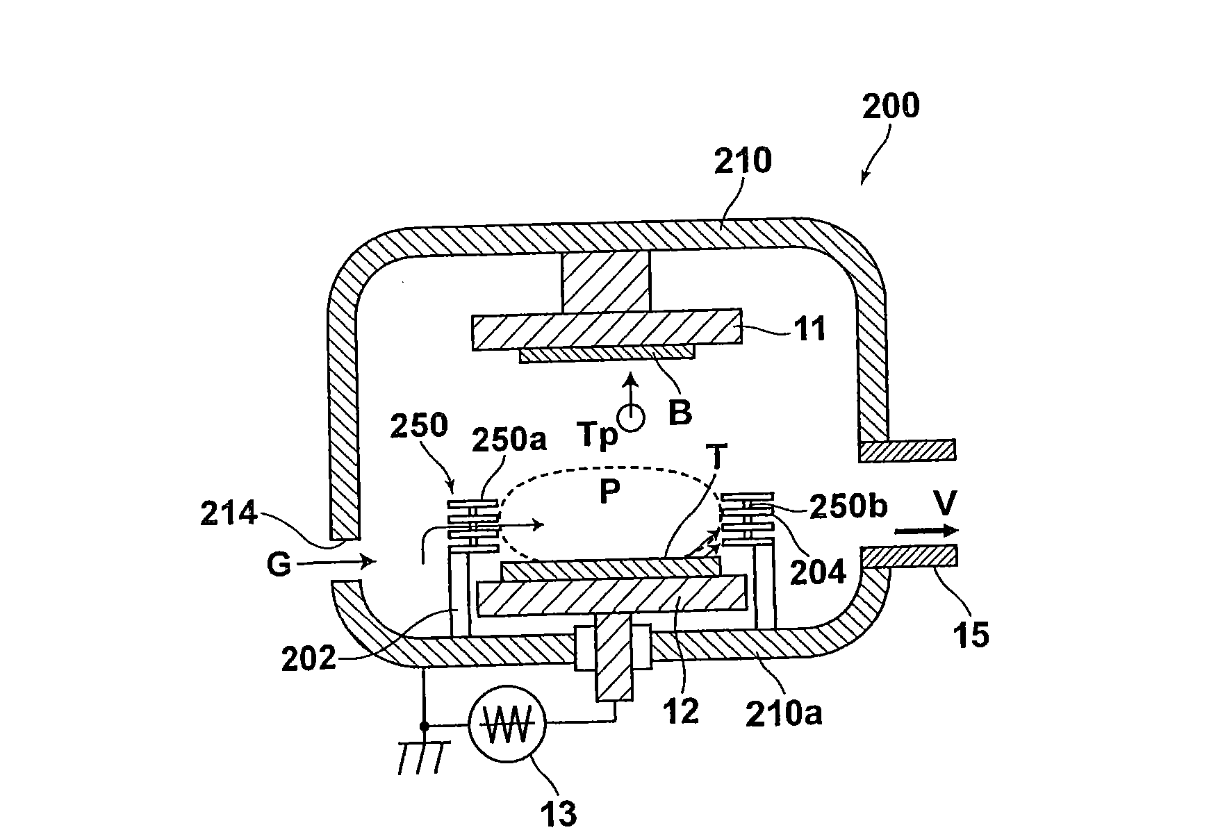
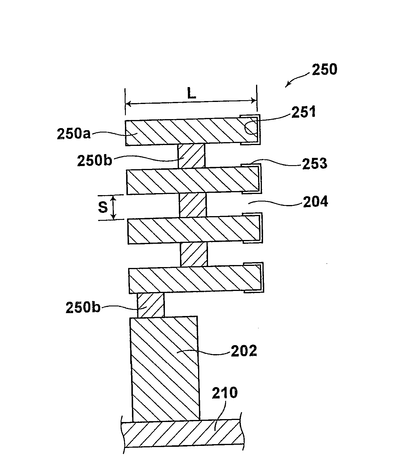
[0169] Prepare a commercially available sputtering device. Five sheets of rings 250 a , 250 a , . . . made of stainless steel (SUS) were set to ground potential and placed along the side of the target T with a diameter of 120 mm in the sputtering apparatus. Each of the rings 250a, 250a, . . . has an inner diameter of 130 mm, an outer diameter of 180 mm, and a thickness of 1 mm. In this way, obtained as Figure 1A The film formation device described in . The rings 250a, 250a, . . . are stacked on top of each other such that columnar conductive spacers 250b, 250b, . Each of the spacers 250b, 250b, ... is substantially smaller in size than each of the rings 250a, 250a, .... Accordingly, the gas G introduced into the vacuum chamber 210 can pass through the space 204 between the adjacent ones 250a, 250a without being adversely affected by the spacers 250b, 250b, . . . , and thus can reach the target T easily.

[0170] The separation distance between the substrate B and the targ...


PUM

PropertyMeasurementUnit
thicknessaaaaaaaaaa
thicknessaaaaaaaaaa
thicknessaaaaaaaaaa

Abstract

Such that at least 5 mol% of donor ions are doped at an A site, a ferroelectric film (40) containing a perovskite type oxide of Formula (P) is formed on a substrate (B) facing a target (T) by sputtering under conditions of a height of a shield (250), which surrounds an outer periphery of the target (T) on the substrate side in a non-contact state and comprises shielding layers (250a, 250a, ...) superposed at intervals, such that a difference between a plasma potential and a floating potential is at most 35V, and under conditions of a substrate temperature of at least 400 DEG C: [Pb( 1-x+delta)Mx ] [Zry Ti (1-y)]Oz ... (P) wherein M represents at least one kind of element selected from Bi and lanthanide elements, 0. 05<=x<=0. 4, and 0<y<=0.7, the standard composition being such that delta=0, and z=3.

Description

technical field [0001] The present invention relates to a method for forming a ferroelectric film containing a PZT-based perovskite-type oxide. The present invention also relates to a ferroelectric film obtained by said method for forming a ferroelectric film. The present invention also relates to a ferroelectric device including the ferroelectric film, and a liquid discharge device using the ferroelectric device. Background technique [0002] Heretofore, a piezoelectric device configured with a piezoelectric body and electrodes for applying an electric field across the piezoelectric body has been used for applications such as an actuator mounted on an inkjet type recording head, the The piezoelectric body has piezoelectric properties such that the piezoelectric body expands and contracts according to the increase and decrease of an applied electric field across the piezoelectric body. As a piezoelectric body material, perovskite-type oxides such as lead zirconate titanate...

Claims


Application Information

Patent Timeline
Patent Type & Authority Applications(China)
IPC IPC(8): C23C14/08C23C14/34H01L41/22H01L41/09H01L41/18H01L21/316B41J2/14B41J2/045B41J2/055B41J2/135B41J2/145B41J2/155B41J2/16C01G23/00C01G25/00C04B35/491H01L41/187H01L41/316H01L41/39
CPCB41J2/155C04B35/493C04B2235/3251H01L41/0805C04B2235/72H01L41/316C04B2235/3227B41J2202/03C23C14/088C04B2235/3258H01L41/1876C23C14/3407C04B2235/3298B41J2/14233H10N30/1051H10N30/8554H10N30/076
Inventor 新川高见藤井隆满
Owner FUJIFILM CORP
Why Eureka
Try Eureka