Adjustable energy-saving catalytic auxiliary heating chamber with low main air pressure drop

An adjustable, main air technology, used in air heaters, fluid heaters, lighting and heating equipment, etc., can solve the problem of large pressure drop of main air supply air, large energy loss of catalytic main fan, and increase the main air power of catalytic system. Consumption and other problems, to achieve the effect of increasing the cross-sectional area of ​​the runner, ensuring the heat utilization efficiency, and avoiding high-frequency vibration accidents

Active Publication Date: 2012-05-09
LUOYANG RUICHANG PETROCHEM EQUIP
View PDF6 Cites 0 Cited by
  • Summary
  • Abstract
  • Description
  • Claims
  • Application Information

AI Technical Summary

Problems solved by technology

When starting up, between the main air inlet of the catalytic auxiliary heating chamber and the heating chamber, the ratio of the air volume of the primary combustion air to the air volume of the mixed secondary air is constant, and the air flow channel of the primary combustion air and the air flow channel of the mixed secondary air are connected in parallel. The flow channel and the pressure drop are equal, which leads to the traditional catalytic auxiliary heating chamber's one-sided pursuit of the combustion effect of the burner's high pressure drop when the device is started, so that the overall main air supply pressure drop of the auxiliary heating chamber is relatively large during the long-term normal operation of the device. , there is a main air pressure drop loss of about 5kPa, resulting in a large energy loss in the long-term operation of the catalytic main fan, thereby increasing the main air power consumption of the entire catalytic system

Method used


Image

  • Adjustable energy-saving catalytic auxiliary heating chamber with low main air pressure drop
  • Adjustable energy-saving catalytic auxiliary heating chamber with low main air pressure drop
  • Adjustable energy-saving catalytic auxiliary heating chamber with low main air pressure drop

Examples


Embodiment Construction

[0030] The present invention is described in conjunction with accompanying drawing and embodiment:

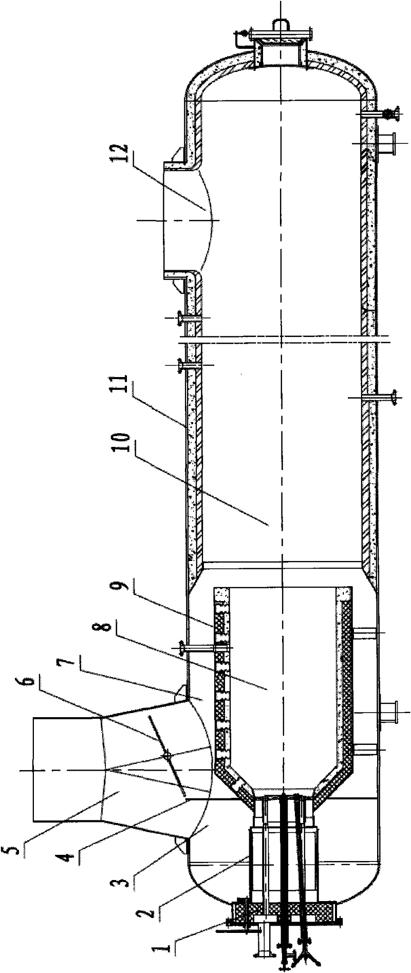
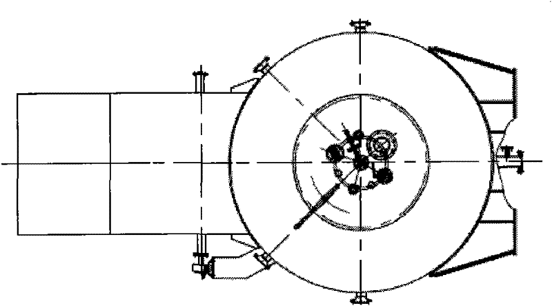
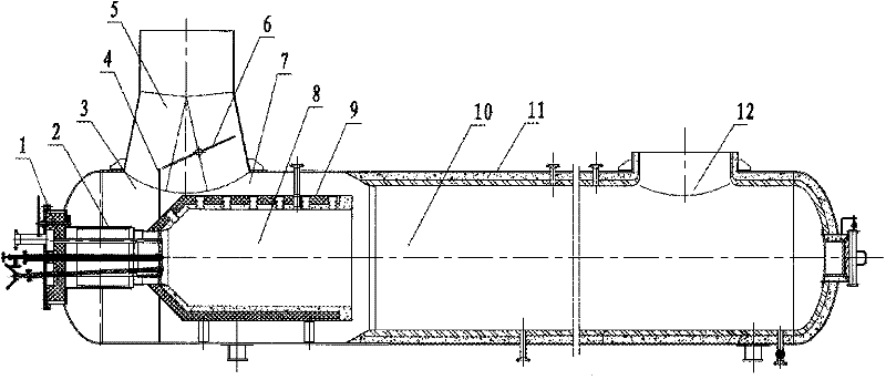
[0031] Such as figure 1 , figure 2 As shown, an adjustable low pressure drop catalytic main air auxiliary heating chamber has a burner 1, a combustion chamber 8, a heating chamber 10 and a main air inlet pipe 5; the burner 1 communicates with the combustion chamber 8; the combustion chamber It consists of a combustion chamber cylinder lined with high-temperature refractory materials; the heating chamber 10 communicates with the combustion chamber 8, and the heating chamber 10 is located at the rear of the combustion chamber 8; the main air inlet pipe 5 is located at the upper part of the combustion chamber and is perpendicular to the combustion chamber Cylinder 9; the upper part of the main air inlet pipe is circular, and its lower part is an expanded oblate cone; the lower part of the main air inlet pipe is divided into the combustion primary air flow channel 3 and the mixin...


PUM


Abstract

The invention relates to a design of a reaction regeneration main air system of an oil refining catalyzing device and provides an adjustable energy-saving catalytic auxiliary heating chamber with low main air pressure drop. The adjustable energy-saving catalytic auxiliary heating chamber is mainly provided with a combustor (1), a combustion chamber (8), a heating chamber (10) and a main air inlet pipe (5), wherein the lower part of the main air inlet pipe which is arranged at the upper part of the combustion chamber and vertical to a cylinder body (9) of the combustion chamber is divided into a combustion primary air passageway (3) and a bending secondary air passageway (7) by a partition board, and the heating chamber (10) is communicated with the bending secondary air passageway (7); the primary air passageway (3) is communicated with the combustor (1) by a combustor air door (2) which can adjust primary air and is arranged on the combustor (1); and a damper regulator (6) for adjusting the air input of the combustion primary air passageway and the bending secondary air passageway is arranged on the bending secondary air passageway in the main air inlet pipe. The invention can reach the high pressure drop combustion effect when the main air of the catalyzing device assists the heating chamber to work, and ensure the running with low pressure drop and power consumption during normal running.

Description

technical field [0001] The invention relates to the design of a reaction regeneration main air system of an oil refinery catalytic device, and mainly proposes an adjustable energy-saving catalytic auxiliary heating chamber with low main air pressure drop. Background technique [0002] At present, the situation facing the realization of energy conservation goals is very severe. The State Council issued a decision to strengthen energy conservation and formulated a series of policies and measures to promote energy conservation. With the development of catalytic cracking technology in the petrochemical industry, improving energy conservation and reducing consumption will also be an inevitable choice. [0003] The purpose of using the auxiliary heating chamber in the reaction regeneration main air system of the catalytic unit of the refinery is to use the heat released by the fuel combustion of the burner in the auxiliary heating chamber of the main air to heat the air supplied b...

Claims


Application Information

Patent Timeline
Patent Type & Authority Patents(China)
IPC IPC(8): F24H3/00B01J38/02
Inventor 吕凤王伟邵松
Owner LUOYANG RUICHANG PETROCHEM EQUIP
Why Eureka
Try Eureka