

Pulse current assisted extrusion forming device and extrusion forming method
A technology of extrusion forming and pulse current, applied in metal extrusion, metal extrusion die, metal extrusion control equipment, etc., can solve the problems of uneven distribution of current density in cross-section, complex process flow, low work efficiency, etc. , to achieve the effect of automatic heating, simple process flow and high production efficiency
- Summary
- Abstract
- Description
- Claims
- Application Information
AI Technical Summary
Problems solved by technology
Method used
Image

Examples
specific Embodiment approach 1
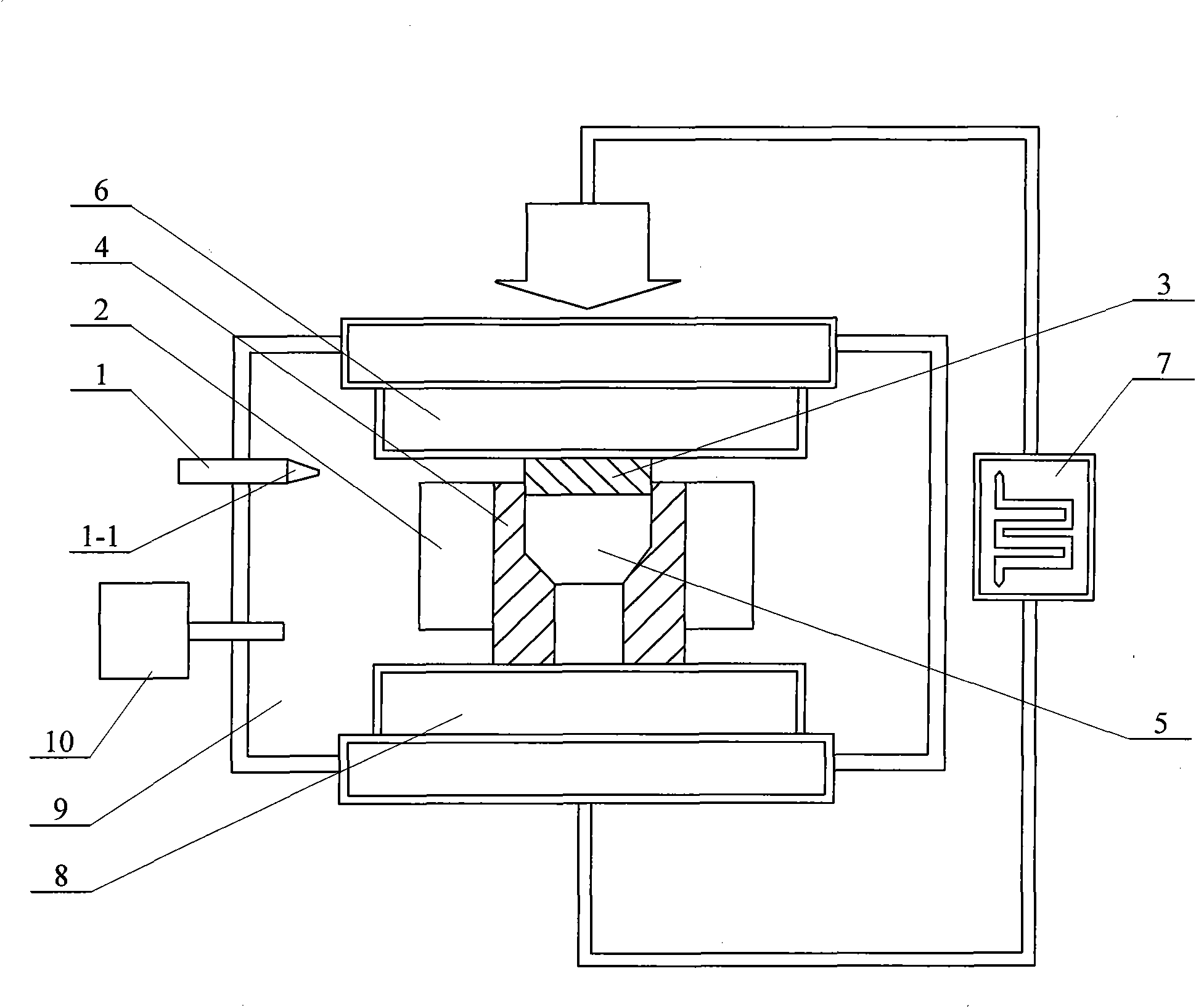
[0020] Specific implementation mode one: combine figure 1 Illustrate present embodiment, the device of present embodiment comprises high-frequency pulse power supply 7, furnace body 9, vacuum system 10, pressurization device and mould; , a conductive punch 3 and a conductive die 4, the pressurizing device is composed of an upper pressure head 6 and a lower pressure head 8, the lower end of the upper pressure head 6 is set on the upper part of the furnace body 9, and the lower pressure head 8 is set on the furnace body 9, the lower end of the conductive die 4 is set on the upper end surface of the lower press head 8, the upper end of the conductive punch 3 is connected to the lower end face of the upper press head 6, and the conductive die 4 is placed in the cavity of the insulating outer film 2 Among them, the conductive convex mold 3 and the conductive concave mold 4 are connected to the high-frequency pulse power supply 7 as electrodes. The conductive punch 3 is the upper e...
specific Embodiment approach 2
[0021] Specific implementation mode two: combination figure 1 This embodiment is described. In this embodiment, the insulating outer film 2 is made of ceramic material, and the outer mold of the insulating ceramic material will not divert the current flowing through the blank to be formed, reducing energy loss. Other compositions and connection methods are the same as those in Embodiment 1.
specific Embodiment approach 3
[0022] Specific implementation mode three: combination figure 1 To illustrate this embodiment, the extrusion molding device described in this embodiment further includes a far-infrared thermometer 1 . The infrared thermometer 1 is provided with a probe 1 - 1 , and the probe 1 - 1 is arranged in the furnace body 9 . The temperature of the billet to be formed is measured in real time by a far-infrared thermometer. Other compositions and connection modes are the same as those in Embodiment 1 or 2.
PUM
 Abstract
Description
Claims
Application Information