Supercharge Your Innovation With Domain-Expert AI Agents!

Heat recovery fresh air unit with distributed cold and heat source

A fresh air unit and heat recovery technology, applied in heat recovery systems, ventilation and heating energy recovery systems, refrigerators, etc., can solve the problem that the fresh air unit cannot meet the comfort requirements of the transition season, cannot handle the fresh air to the required state, and the fresh air unit Inability to work alone, etc., to achieve the effect of improving air quality, performance, and high energy efficiency ratio

Inactive Publication Date: 2010-03-17
TONGFANG ARTIFICIAL ENVIRONMENT
View PDF0 Cites 28 Cited by
  • Summary
  • Abstract
  • Description
  • Claims
  • Application Information

AI Technical Summary

Problems solved by technology

Since this heat recovery device is driven by temperature difference or enthalpy difference, the general recovery efficiency is less than 70%.
In addition, the fresh air cannot be processed to the required state solely by the recovery function, and the centralized cold and heat source of the air conditioning system is required for follow-up processing. Therefore, the fresh air unit with heat recovery function cannot work alone
In the transitional season, when the centralized cooling and heating source is not in use, the fresh air unit that simply relies on the fixed fresh air volume (generally only meets the basic requirements of personnel) cannot meet the comfort requirements of the transitional season

Method used


Image

  • Heat recovery fresh air unit with distributed cold and heat source

Examples


Embodiment Construction

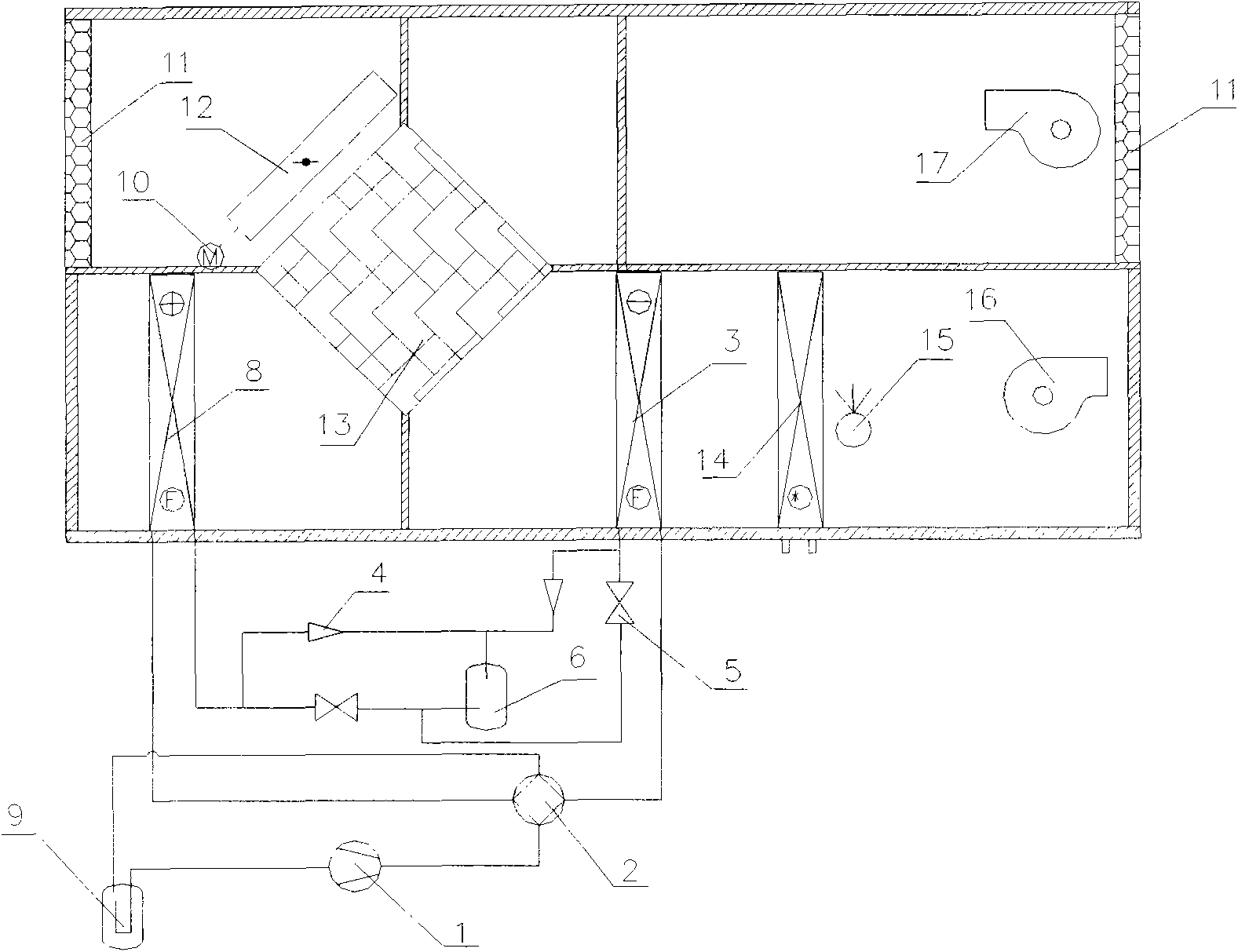
[0015] Referring to the accompanying drawings, the fresh air unit of the present invention is composed of a heat pump system and a ventilation system. The heat pump system consists of a compressor 1, a four-way valve 2, a one-way valve 4, an expansion valve 5, a liquid receiver 6, a gas-liquid separator 9, a condenser 3 and an evaporator 8 to form an air-conditioning refrigeration and heating system. The ventilation system consists of a filter 11, a fresh air side ventilation valve 12, a side ventilation valve controller 10, a heat recovery heat exchanger 13, a water coil 14, a humidifier 15, a blower 16 and an exhaust fan 17. The condenser 3 and the evaporator 8 in the heat pump system are separated and placed in the ventilation system. The condenser 3 is placed at the air inlet outlet of the heat recovery heat exchanger 13 , and the evaporator 8 is placed at the exhaust air outlet of the heat recovery heat exchanger 13 .

[0016] When the present invention works, following ...


PUM


Abstract

The invention discloses a heat recovery fresh air unit with a distributed cold and heat source, belonging to a fresh air unit in the technical field of air conditioning. The heat recovery fresh air unit with the distributed cold and heat source comprises a heat pump system and a ventilating system, wherein the heat pump system comprises a compressor, a four-way valve, a one-way valve, an expansionvalve, a reservoir, a gas-liquid separator, a condenser and an evaporator which form an air conditioning refrigerating and heating system; and the ventilating system comprises a filter, a fresh air bypass ventilating valve, a bypass ventilating valve controller, a heat recovery heat exchanger, a water coil pipe, a humidifier, a blower and an exhaust fan. The invention has the structural characteristic that the condenser and the evaporator in the heat pump system are separately arranged in the ventilating system, wherein the condenser is arranged at the intake air outlet of the heat recovery heat exchanger, and the evaporator is arranged at the exhaust air outlet of the heat recovery heat exchanger. Under the condition that a centralized cold and heat source is not used, the invention cancarry out temperature reduction and dehumidification or heating and humidification on fresh air, and exchange the indoor air, improve the indoor comfort level, realize higher heat recovery efficiency,and simultaneously have higher energy efficiency ratio.

Description

technical field [0001] The invention belongs to fresh air units in the technical field of air conditioning, in particular to heat recovery fresh air units with distributed cold and heat sources. Background technique [0002] The fresh air unit is an air-conditioning device that provides fresh air. The working principle is to extract fresh air from the outside and send it to the room through the fan after dust removal, dehumidification (or humidification), cooling (or heating) and other treatments, and replace the original indoor air when entering the indoor space. [0003] Most of the existing fresh air units include a filter section, a surface cooling section, a heating section, and a fan section, and the outdoor fresh air is sent indoors after temperature and humidity treatment. Among them, the functions of cooling, dehumidification and heating are provided by the centralized cold and heat source of the air conditioning system. In the excessive season, when the centraliz...

Claims


Application Information

Patent Timeline
IPC IPC(8): F24F12/00F25B13/00F25B30/02
CPCY02B30/16Y02B30/123Y02B30/52Y02B30/563Y02B30/56
Inventor 范新赵庆珠张乐平谢峤王青平
Owner TONGFANG ARTIFICIAL ENVIRONMENT
Features
  • R&D
  • Intellectual Property
  • Life Sciences
  • Materials
  • Tech Scout
  • Unparalleled Data Quality
  • Higher Quality Content
  • 60% Fewer Hallucinations
Learn More