Curved channel waveguide slow-wave line

A technology of meandering slots and slow wave lines, which is applied in the field of microwave electron tubes, can solve the problems of increased loss, small size, and restrictions on meandering rectangular waveguide slow wave lines, etc., and achieve the goals of improving output power and efficiency, increasing output power, and large output power Effect

Inactive Publication Date: 2010-03-17
UNIV OF ELECTRONICS SCI & TECH OF CHINA
View PDF0 Cites 7 Cited by
  • Summary
  • Abstract
  • Description
  • Claims
  • Application Information

AI Technical Summary

Problems solved by technology

[0010] When the ordinary rectangular waveguide works in the millimeter wave, especially the short millimeter wave band, the size will become very small, which greatly limits the power capacity of the transmitted microwave, and at the same time, the loss increases rapidly; therefore, the meandering rectangular waveguide slow wave based on the rectangular waveguide When the line works to the millimeter wave, especially the short millimeter wave band, it also has the defects of small size, low power capacity for transmitting microwaves, and increased loss, which greatly limits the application of the meandering rectangular waveguide slow wave line

Method used


Image

  • Curved channel waveguide slow-wave line
  • Curved channel waveguide slow-wave line
  • Curved channel waveguide slow-wave line

Examples


Embodiment Construction

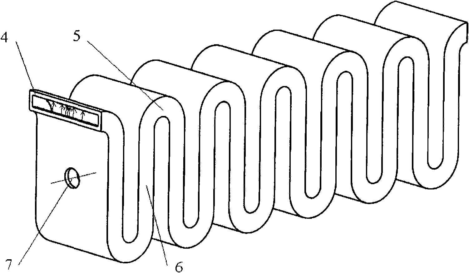
[0032] Figure 5 and Figure 7 Two specific implementations of meandering slot waveguide slow wave lines are given.

[0033] Figure 5 It is a three-dimensional structural schematic diagram of a waveguide slow wave line with a meandering circular arc groove. Here, in order to clearly see the meandering situation of the groove, the thickness of the metal plate is ignored; at the same time, the support wall between the upper and lower metal plates is ignored.

[0034] Figure 7 It is a three-dimensional structural schematic diagram of a meandering rectangular slot waveguide slow wave line. The upper and lower metal plates should be formed by directly digging zigzag grooves on metal plates with a certain thickness, and Figure 6 similar. Here, the thickness of the metal plate is ignored in order to clearly see the twists and turns of the groove. Beryllium oxide ceramic strips 11 are used for support between the upper and lower metal plates.


PUM


Abstract

The invention relates to a curved channel waveguide slow-wave line, belonging to the technical field of microwave electronic tubes and relating to a slow-wave line structure in a microwave tube high-frequency system. The slow-wave line is formed by bending the channel back and forth by the channel waveguide along a direction of the channel; an electric field of a ground mode in the channel waveguide is the strongest on the vertical axis of the slow-wave line and generates the strongest interaction right with an electron bunch; a gap is left between an upper metal plate and a lower metal plateof the channel waveguide without special electron bunch channels; and a side wall for supporting the gap between the upper and lower metal plates can be made of metal, insulating materials or microwave absorption materials. The curved channel waveguide keeps the advantages of large size, low consumption and wide band of the channel waveguide, and the curved channel waveguide slow-wave line also allows large-size electron bunch to pass through, thereby having higher output power and efficiency. At the same time, the slow-wave line has the characteristics of relatively simple structure, low processing precision requirement and easy processing. The curved channel waveguide slow-wave line is more suitable to be applied in the travelling wave tube of the wave segments of millimeter wave and submillimeter wave.

Description

technical field [0001] The invention belongs to the technical field of microwave electron tubes, and relates to a slow wave line structure in a microwave tube high-frequency system. Background technique [0002] When the ordinary waveguide used as a microwave transmission line works in the millimeter wave, especially the short millimeter wave band, the size will become very small, which greatly limits the power capacity of microwave transmission, and at the same time, the loss increases rapidly. For example, at 200GHz frequency, rectangular The size of the waveguide is only 1.092mm×0.546mm, the theoretical loss reaches 9.7dB / m, and the actual measured loss is as high as 40dB / m. Although the overmode waveguide can increase the size of the waveguide, there is serious high-order mode competition. [0003] Slot waveguide is a waveguide transmission line proposed in the 1960s, such as figure 1 As shown, it consists of upper and lower metal plates 1, 2, and a groove 3 processed o...

Claims


Application Information

Patent Timeline
Patent Type & Authority Applications(China)
IPC IPC(8): H01P9/00
Inventor 王文祥唐涛岳玲娜赵国庆魏彦玉宫玉彬
Owner UNIV OF ELECTRONICS SCI & TECH OF CHINA
Why Eureka
Try Eureka