Method for manufacturing plasma display panel

A technology of a plasma display and a manufacturing method, which are applied in the direction of alternating current plasma display panels, the manufacture of discharge tubes/lamps, and the manufacture of cold cathodes, etc., can solve the problems of reducing the attenuation rate and the like

Inactive Publication Date: 2010-03-24
PANASONIC CORP
View PDF2 Cites 0 Cited by
  • Summary
  • Abstract
  • Description
  • Claims
  • Application Information

AI Technical Summary

Problems solved by technology

[0009] In this way, there is a problem that as a protective layer, it is necessary to maintain both high electron emiss

Method used


Image

  • Method for manufacturing plasma display panel
  • Method for manufacturing plasma display panel
  • Method for manufacturing plasma display panel

Examples


Embodiment approach

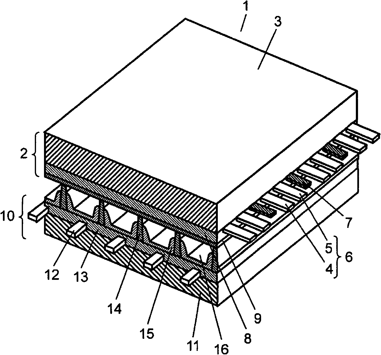
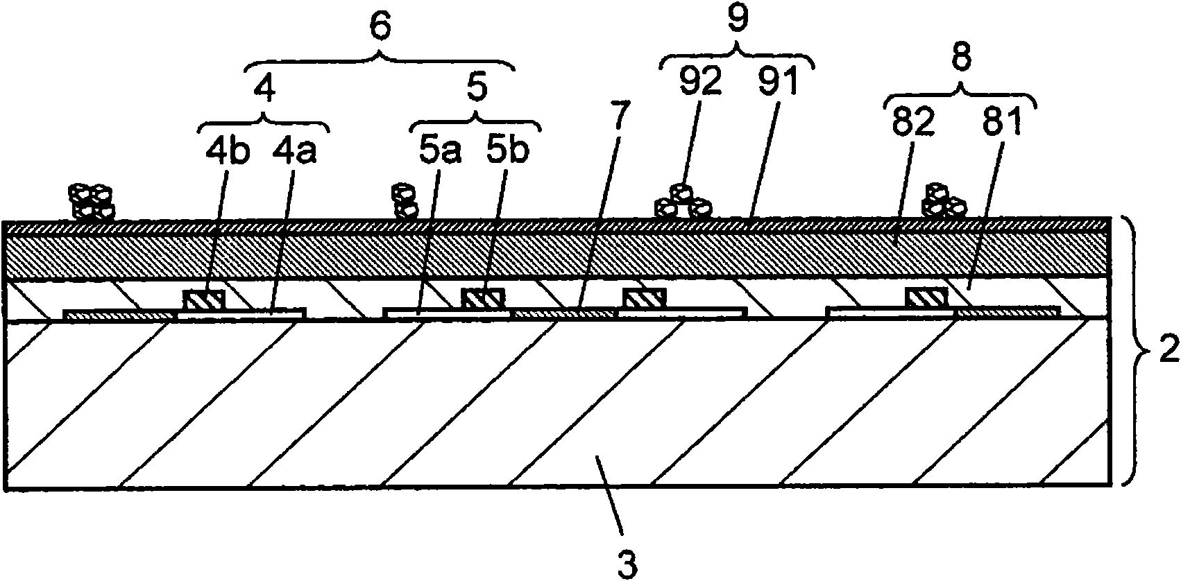
[0048] figure 1 It is a perspective view showing the structure of PDP 1 manufactured by the PDP manufacturing method in the embodiment of the present invention. Front panel 2 including front glass substrate 3 and rear panel 10 including rear glass substrate 11 are arranged to face each other, and the outer periphery thereof is hermetically sealed with a sealing material including glass frit. In the discharge space 16 inside the PDP 1, discharge gases such as neon (Ne) and xenon (Xe) are sealed at a pressure of 53.3 kPa to 80.0 kPa. On the front glass substrate 3 of the front panel 2, a pair of strip-shaped display electrodes 6 and black stripes (light shielding layers) 7 composed of scan electrodes 4 and sustain electrodes 5 are arranged in parallel to each other. A dielectric layer 8 functioning as a capacitor is formed on the front glass substrate 3 to cover the display electrodes 6 and the light shielding layer 7, and a protective layer 9 made of magnesium oxide (MgO) or t...


PUM


Abstract

Provided is a plasma display panel which has highly fine and high-luminance display characteristics and low power consumption. After forming a base film (91), a metal oxide paste composed of metal oxide grains, an organic resin component and a diluting solvent is applied and fired so as to form the plurality of metal oxide grains by adhering the grains on the base film (91). The metal oxide pastecontains metal oxide grains of 1.5 vol% or less, and the content of the organic resin component is 8.0-20.0 vol%.

Description

technical field [0001] The present invention relates to a method of manufacturing a plasma display panel. Background technique [0002] Plasma display panels (hereinafter referred to as PDPs) are widely used in fields such as video display devices and promotional display devices because they can display at high speed even in flat panel displays (FPDs) and are easy to increase in size. [0003] Generally, an AC-driven surface discharge type PDP has a three-electrode structure, and two glass substrates, a front panel and a rear panel, are configured to face each other at a predetermined interval. The front panel is composed of the following components: stripe-shaped display electrodes composed of scan electrodes and sustain electrodes formed on a glass substrate; a dielectric layer covering the display electrodes and functioning as a capacitor for accumulating charges; A protective film with a thickness of about 1 μm. On the other hand, the back panel is composed of the foll...

Claims


Application Information

Patent Timeline
IPC IPC(8): H01J9/02H01J11/02H01J11/12H01J11/22H01J11/24H01J11/26H01J11/34H01J11/36H01J11/40
CPCH01J11/40H01J9/02H01J11/12H01J11/38
Inventor 石野真一郎坂元光洋宫前雄一郎沟上要大江良尚
Owner PANASONIC CORP
Why Eureka
Try Eureka