Integrated circuit, optical disc device and tracking error signal generating method
An integrated circuit and tracking error technology, which is applied in the field of generating tracking error signals, can solve the problem of difficult to cope with the high density of optical recording media with doubled speed of optical disc devices, and achieve the effects of reducing area, circuit scale and cost.
- Summary
- Abstract
- Description
- Claims
- Application Information
AI Technical Summary
Problems solved by technology
Method used
Image


Examples
Embodiment approach 1
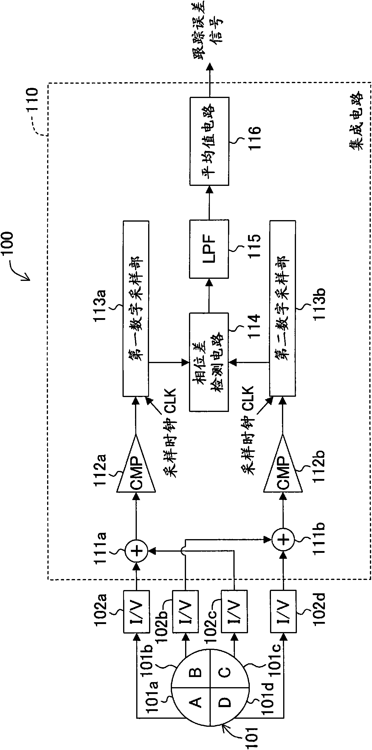
[0038] The optical disc device according to Embodiment 1 has figure 1 The tracking error detection device 100 is shown. The tracking error detection device 100 includes a four-quadrant photodetector 101 , four current-to-voltage converters 102 a - 102 d and an integrated circuit 110 .
[0039] The four-quadrant photodetector 101 has four light receiving surfaces 101a to 101d as A channel, B channel, C channel and D channel, and outputs a photocurrent corresponding to the amount of light received by each of the light receiving surfaces 101a to 101d. Here, the light receiving surface 101a and the light receiving surface 101c correspond to the first light receiving surface in the claims, and the light receiving surface 101b and the light receiving surface 101d correspond to the second light receiving surface in the claims.
[0040] The current-to-voltage converter 102a converts the photocurrent corresponding to the amount of light received by the light-receiving surface 101a in...
Embodiment approach 2
[0061] An optical disc device according to Embodiment 2 of the present invention, instead of the tracking error detection device 100 according to Embodiment 1, has figure 2 The tracking error detection device 200 is shown. The tracking error detection device 200 has an integrated circuit 210 instead of the integrated circuit 110 of the tracking error detection device 100 . This integrated circuit 210 includes a sampling frequency setting unit 211 and a low-pass filter control unit 212 in addition to the configuration of the integrated circuit 110 according to the first embodiment. Other configurations and operations of the optical disc device of this embodiment are the same as those of Embodiment 1, and therefore detailed description thereof will be omitted.
[0062] The sampling frequency setting part 211 sets the sampling frequency of the first digital sampling part 113a and the sampling frequency of the second digital sampling part 113b to a frequency different from an int...
Embodiment approach 3
[0067] An optical disc device according to Embodiment 3 of the present invention, instead of the tracking error detection device 100 according to Embodiment 1, has image 3 The tracking error detection device 300 is shown. The tracking error detection device 300 has an integrated circuit 310 instead of the integrated circuit 110 of the tracking error detection device 100 . This integrated circuit 310 includes a first delay circuit 311 a , a second delay circuit 311 b , and a delay amount control unit (controller) 312 in addition to the configuration of the integrated circuit 110 of Embodiment 1. Other configurations and operations of the optical disc device of this embodiment are the same as those of Embodiment 1, and therefore detailed description thereof will be omitted.
[0068] The first delay circuit 311a delays the first binarized signal output from the first comparator 112a before inputting the first binarized signal to the first digital sampling unit 113a.
[0069] T...
PUM
 Abstract
Description
Claims
Application Information