Hydraulic pump flow regulating device

A technology of flow regulating device and hydraulic pump, which is applied in the direction of fluid pressure actuating device, servo motor assembly, mechanical equipment, etc., can solve the problem of high cost, and achieve the effect of improving oil absorption capacity, reducing cost and increasing working speed.

Inactive Publication Date: 2010-04-07
TAIYUAN UNIV OF TECH
View PDF2 Cites 23 Cited by
  • Summary
  • Abstract
  • Description
  • Claims
  • Application Information

AI Technical Summary

Problems solved by technology

[0005] The purpose of the hydraulic pump flow regulating device of the present invention is to control the output flow of the hydraulic pump in a relatively large range through the combination of the hydraulic pump and the use of a small power variable speed motor, so as to solve the problem of using a servo motor to drive a high-power system in the prior art. High problem, thus providing a hydraulic pump flow adjustment device

Method used


Image

  • Hydraulic pump flow regulating device
  • Hydraulic pump flow regulating device
  • Hydraulic pump flow regulating device

Examples


Embodiment 1

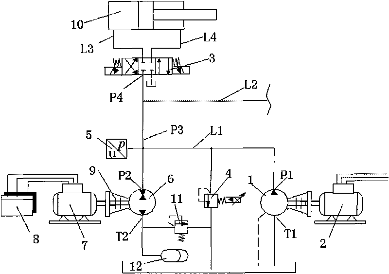
[0020] figure 1 It is the first embodiment of the present invention. The adjusting device of the hydraulic pump flow comprises a one-way rotary hydraulic pump 1, a power source 2, a control valve 3, an overflow valve 4, a pressure sensor 5 and a hydraulic actuator 10, and its composition is that the present invention is based on the existing hydraulic pump flow adjustment. In the system, a two-way rotating hydraulic pump 6, a motor 7, a motor speed controller 8, a shaft coupling 9, a safety valve 11 and an accumulator 12 are further added. Wherein, the power source 2 drives the one-way rotary hydraulic pump 1, the oil outlet P1 of the one-way rotary hydraulic pump 1 communicates with the first oil port P2 of the two-way rotary hydraulic pump 6 through the first hydraulic pipeline L1, and the total oil outlet P3 It communicates with the first hydraulic pipeline L1, which is the common oil outlet of two hydraulic pumps, the one-way rotary hydraulic pump 1 and the two-way rotar...

Embodiment 2

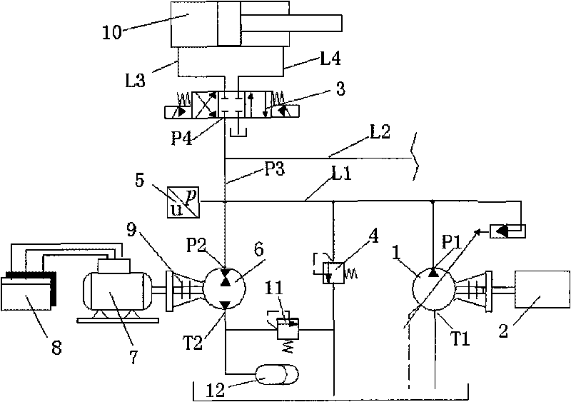
[0024] figure 2 It is the second embodiment of the present invention. The difference with the first embodiment is: 1) The selected one-way rotary hydraulic pump 1 is a mechanically adjusted constant power type variable hydraulic pump, its displacement is equal to that of the two-way rotary hydraulic pump 2, and its output flow It has a hyperbolic relationship with the pressure at the pump outlet P1, that is, the product of the two is a constant value, thus limiting the maximum output power of the one-way rotary hydraulic pump 1 . 2) The power source 2 adopts an internal combustion engine, driven by diesel or gasoline. In addition, the composition, connection relationship and working principle of the system are exactly the same as those of Embodiment 1, and it can be applied in hybrid-driven traveling machinery, such as excavators, loaders and tractors.

Embodiment 3

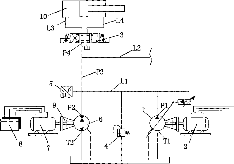
[0026] image 3 It is the third embodiment of the present invention. The differences from the first embodiment are as follows: 1) The selected one-way rotary hydraulic pump 1 is a constant pressure variable pump controlled by electronic proportion, which can be controlled continuously proportionally by changing the current signal of the proportional pilot valve integrated on it. The pressure value at the pump outlet. 2) The safety valve 11 and the accumulator 12 are removed, and the second oil port T2 of the two-way rotary hydraulic pump 6 communicates directly with the oil tank T. In addition, the composition, connection relationship and working principle of the system are exactly the same as those in Embodiment 1. The characteristic of the system is that it can continuously control the flow and pressure supplied to the hydraulic actuator 10 through the main oil outlet P3, which can be applied to injection molding machines, Presses, die-casting machines, balers and other in...


PUM


Abstract

The invention relates to a hydraulic pump flow regulating device which is characterized in that a flow regulating system is additionally arranged in a system, i.e. a motor drives a bidirectional rotation hydraulic pump through a shaft coupling; a motor rotation speed controller controls the direction and magnitude of rotation of the motor; a first oil port of the bidirectional rotation hydraulic pump is communicated with an oil outlet of a unidirectional rotation hydraulic pump through a hydraulic tube; the hydraulic tube is communicated with a main oil outlet; the main oil outlet is communicated with an oil inlet of a control valve; and a second oil port of the bidirectional rotation hydraulic pump is communicated with an energy accumulator and a safety valve. The invention uses a servo motor with smaller power to continuously control the output flow of the whole hydraulic system in a lager power range, thereby reducing the control cost of the system; the bidirectional rotation hydraulic pump is adopted to enable the system to have an energy storage function; and the second oil port of the bidirectional rotation hydraulic pump is communicated with the energy accumulator, thereby improving the oil absorbing ability and the working rotation speed of the pump. The invention is suitable for traveling machinery driven by hybrid power.

Description

technical field [0001] The invention relates to a flow regulating device of a hydraulic pump, which belongs to the technical field of electro-hydraulic control, in particular to a device for continuously controlling the output flow of a hydraulic pump by changing the rotating speed of the pump. Background technique [0002] In order to reduce the energy loss and calorific value of the hydraulic system, a development trend of hydraulic control technology is to control the output flow of the pump by changing the speed of the hydraulic pump. For example: the invention patent of a "low idling energy consumption hydraulic power source" with the publication number CN1821574A discloses that such a system is equipped with a displacement sensor that can detect the displacement of the pump, and the power can be changed by changing the speed of the pump. The source has the composite function of constant pressure, constant current and constant power control, and reduces the energy consu...

Claims


Application Information

Patent Timeline
Patent Type & Authority Applications(China)
IPC IPC(8): F15B13/02F15B15/18
Inventor 权龙王成宾
Owner TAIYUAN UNIV OF TECH
Why Eureka
Try Eureka