Aluminum fin material for heat exchanger

A technology of heat exchangers and aluminum fins, applied in the field of fin materials, can solve the problems of deodorization performance decline, loss of deodorization performance, etc.

Inactive Publication Date: 2010-04-07
KOBE STEEL LTD
View PDF2 Cites 5 Cited by
  • Summary
  • Abstract
  • Description
  • Claims
  • Application Information

AI Technical Summary

Problems solved by technology

[0003] However, in terms of technology using adsorption, as the amount of adsorption of odorous components adsorbed to the deodorant accumulates, its deodorizing performance decreases until it reaches a saturated state of adsorption and then loses the deodorizing performance. Conversely, the deodorant has Danger of becoming source of bad smell
In addition, in terms of technology using photocatalysts, since light such as ultraviolet rays is required to express deodorization performance, there are problems such as the need to install a light source for light irradiation and a light source introduction hole.

Method used


Image

  • Aluminum fin material for heat exchanger
  • Aluminum fin material for heat exchanger
  • Aluminum fin material for heat exchanger

Examples


no. 1 Embodiment approach 》

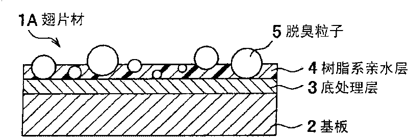
[0020] figure 1 It is a cross-sectional view showing a schematic structure of an aluminum fin material for a heat exchanger (hereinafter referred to as a "fin material") according to the first embodiment of the present invention. This fin material 1A has a substrate 2 made of aluminum (Al) or an Al alloy, a primer layer 3 disposed on the substrate 2, and a resin-based hydrophilic layer 4 disposed on the primer layer 3, and the deodorizing particles 5 are coated with resin. The resin-based hydrophilic layer 4 remains exposed on the surface of the resin-based hydrophilic layer 4 .

[0021] Although in figure 1 In the figure, the method in which the primer treatment layer 3 and the resin-based hydrophilic layer 4 are provided on only one side of the substrate 2 is shown, but the primer treatment layer 3 and the resin-based hydrophilic layer 4 may be provided on both surfaces of the substrate 2 . In addition, in order to improve the corrosion resistance of the fin material 1A, a...

no. 2 Embodiment approach 》

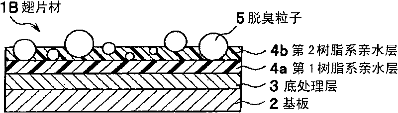
[0045] figure 2 is a cross-sectional view showing a schematic structure of a fin material according to a second embodiment of the present invention. This fin material 1B has a substrate 2, a primer layer 3 provided on the substrate 2, a first resin-based hydrophilic layer 4a provided on the primer layer 3, and a first resin-based hydrophilic layer 4a provided on the first resin-based hydrophilic layer 4a. The second resin-based hydrophilic layer 4b. The deodorizing particles 5 are held by the resin-based hydrophilic layer 4b so as to be exposed on the surface of the second resin-based hydrophilic layer 4b, so that a good deodorizing effect can be obtained from the initial stage. In the fin material 1B, the total film thickness of the first resin-based hydrophilic layer 4 a and the second resin-based hydrophilic layer 4 b is set to 0.05 to 5 μm for the same reason as the fin material 1A described above, preferably 0.2~2μm. The same applies to the fin materials 1C and 1D des...

no. 3 Embodiment approach 》

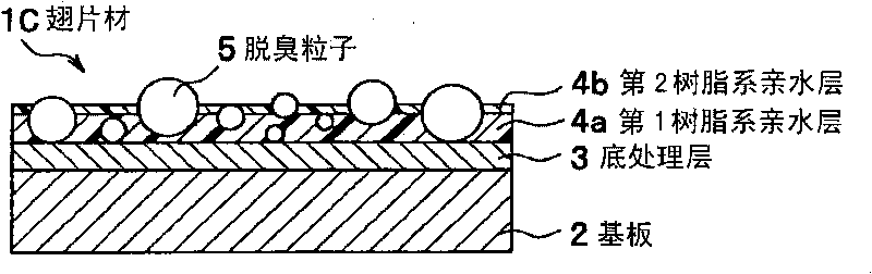
[0048] image 3 It is a cross-sectional view showing a schematic structure of a fin material according to a third embodiment of the present invention. This fin material 1C has a substrate 2, a primer layer 3 provided on the substrate 2, a first resin-based hydrophilic layer 4a provided on the primer layer 3, and a first resin-based hydrophilic layer 4a provided on the first resin-based hydrophilic layer 4a. In the second resin-based hydrophilic layer 4b, the deodorizing particles 5 are held by the first resin-based hydrophilic layer 4a so as to be exposed on the surface of the second resin-based hydrophilic layer 4b.

[0049] The substrate 2 , the primer layer 3 , and the deodorizing particles 5 constituting the fin material 1C are the same as those used for the fin material 1A. The first resin-based hydrophilic layer 4a is composed of the above-mentioned poorly soluble hydrophilic resin, and the second resin-based hydrophilic layer 4b is composed of the above-mentioned water...


PUM

PropertyMeasurementUnit
thicknessaaaaaaaaaa
thicknessaaaaaaaaaa
thicknessaaaaaaaaaa

Abstract

To provide an aluminum fin material for a heat exchanger which does not need an ancillary facility such as a light source to be provided and capable of obtaining superior deodorizing performance by controlling the accumulation of an adsorption amount of an odor component. The fin material includes a substrate comprising Al or an Al alloy, a base treatment layer provided on the substrate, a resin-based hydrophilic layer having a film thickness of 0.05-5 [mu]m provided on the base treatment layer, and deodorizing particles having an average particle diameter larger than the film thickness of the resin-based hydrophilic layer by 0.05-100 [mu]m and held by the resin-based hydrophilic layer to be exposed on the surface of the resin-based hydrophilic layer. As the deodorizing particles, one or both of a metal complex having an oxidizing and reducing action, for example, particles comprising an Fe phthalocyanine complex and a Co phthalocyanine complex, and a non-organic compound having a neutralizing action, for example, particles comprising a non-organic compound containing Zr and P, are used.

Description

technical field [0001] The invention relates to a fin material with aluminum or aluminum alloy as the base material, in particular to an aluminum fin material for heat exchangers with deodorizing performance. Background technique [0002] In recent years, the airtightness of houses has been improved, and with increasing concern for health and the environment, air conditioners can be used to remove smoke odors, pet odors, and volatile organic compounds emitted from building materials from living spaces. Stink etc. For example, a deodorizing total heat exchanger is known, which is composed of a honeycomb structure that combines activated carbon having a function of adsorbing odorous components with silica gel, and has deodorizing properties while maintaining deodorizing properties. Moisture exchange property (for example, refer to JP-A-58-182097). In addition, as a technique utilizing photocatalysts, there is known a heat exchanger having a structure in which an oxidation ca...

Claims


Application Information

Patent Timeline
Patent Type & Authority Applications(China)
IPC IPC(8): F28F21/08F28F19/02C09D5/00
Inventor 清水高宏馆山庆太太田阳介
Owner KOBE STEEL LTD
Why Eureka
Try Eureka